My Plessey Peripherals based PDP-11
How things started
In the late 80’s, when I was no longer working with PDP‑11 computers but with IBM hosts and networks, I got the chance to get a Plessey PDP‑11. It was a small cabinet with everything but without documentation. Unfortunately I did not know too much about how to preserve a PDP‑11 and instead of keeping everything together I started to take it apart and disposed of things that apparently did no longer work or which I had no possibility to get the necessary parts to repair it. Further adding to the dilemma was the limited space in my flat and intermittent changes in hobbies so that at the end the only thing I kept was the backplane and the cards.
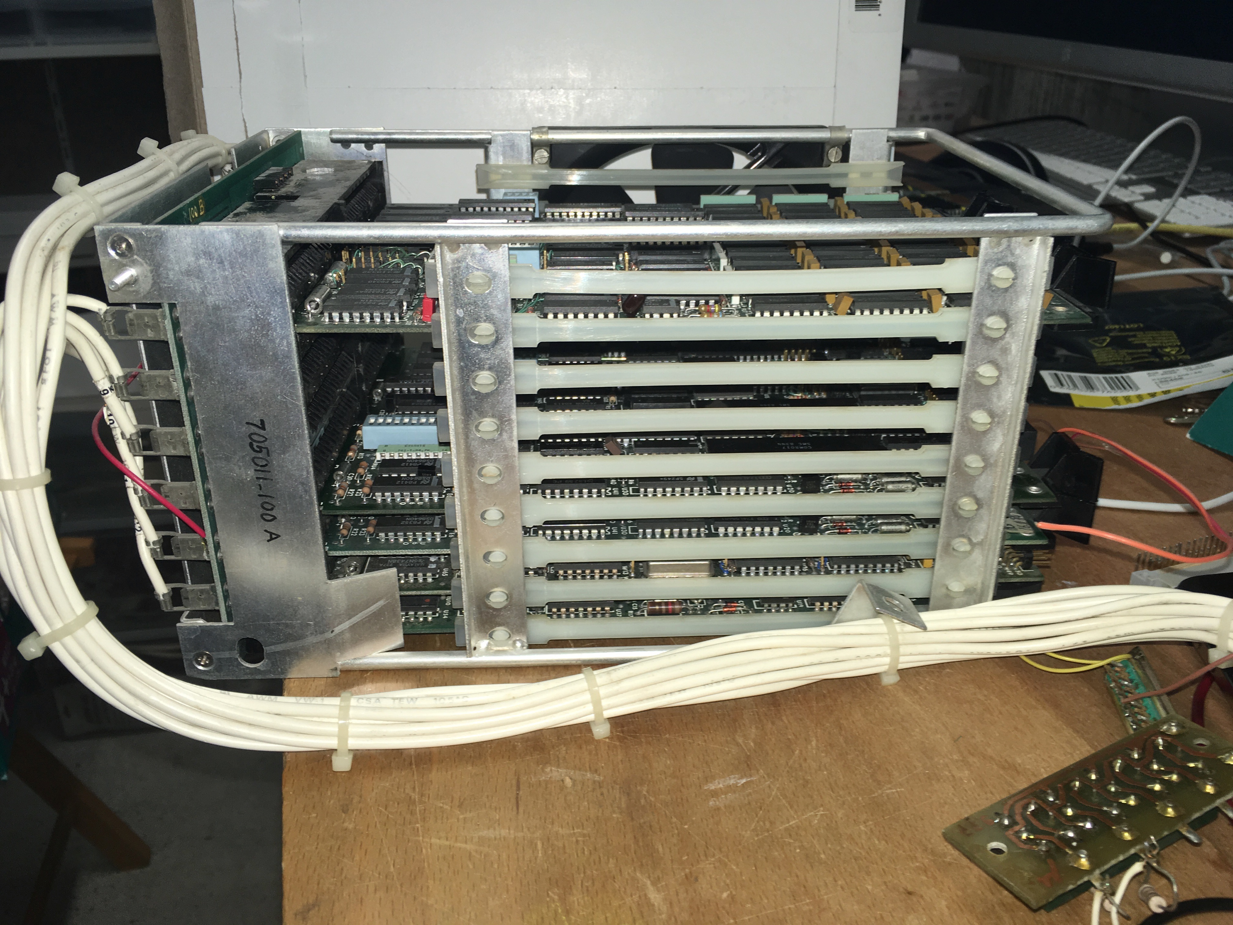
The system consisted of a Plessey backplane with 9 dual-width slots and a DEC M8186 CPU board and a lot of Plessey Peripherals cards. These cards were emulating standard DEC cards. Little did I know about the system and it actually worked only by chance as long as I did not change the amount and order of the installed cards. The original system consisted of the maximum of 9 cards. But more about this later.
The Documentation
There was almost no documentation, unfortunately the department owning the system has already thrown away everything when they were dismantling the system. There have been specific days for the disposal of different materials and when I learned about the system the date for paper disposal was over and so the only thing I could rescue was the cabinet. Later I got in contact with an engineer of my previous employer who had same very sparse documentation about Plessey Peripherls systems and was kind enough to FAX them (at that time an international fax of about 20 pages was rather expensive) and up to now this is the only documentation I have. These pages only describe the power consumption and the jumper settings of some cards. Not much but enough to reanimate the system. I have scanned the pages and have added them to this post. You will find a download link in each appropriate chapter.
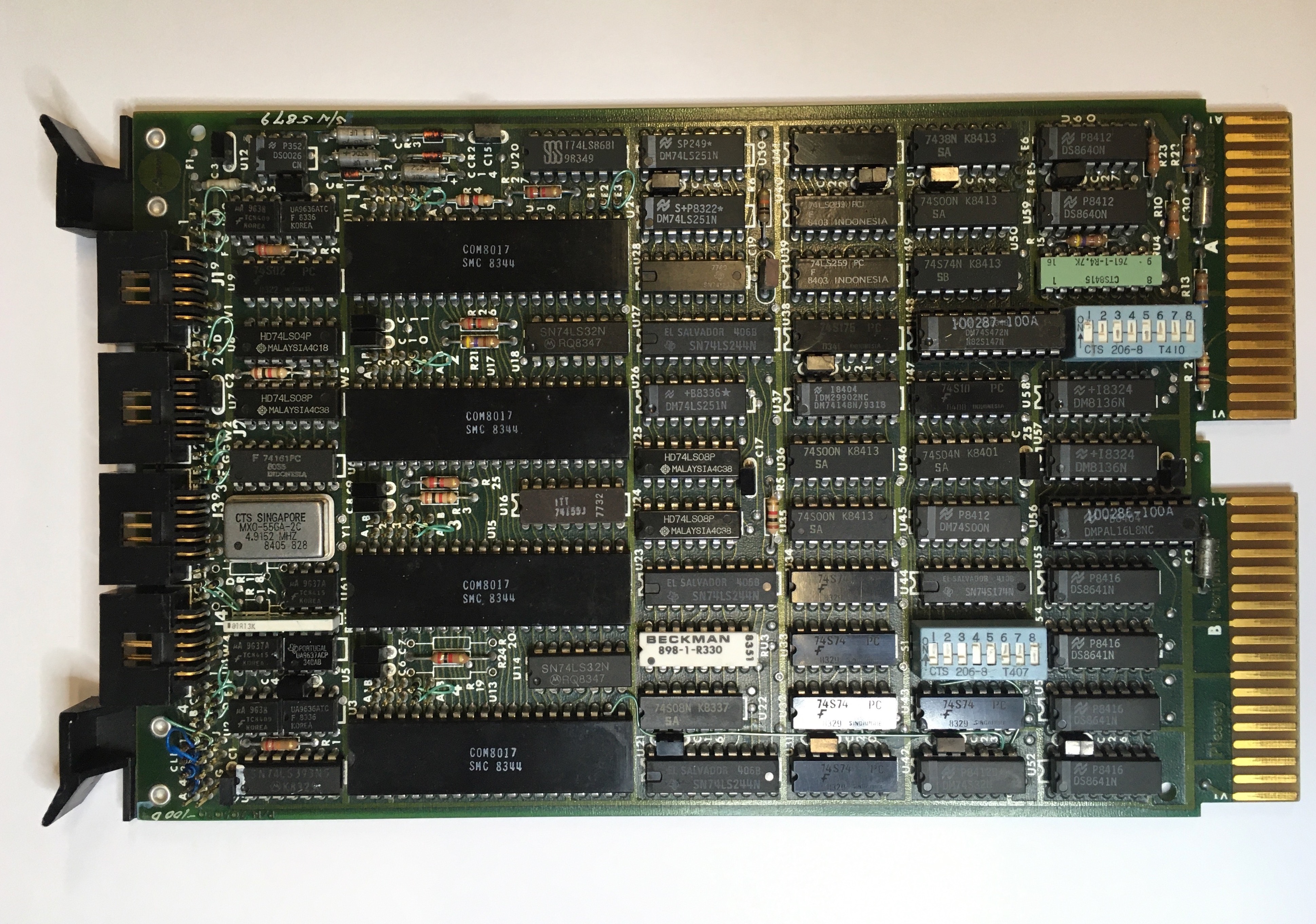
List of Plessey Peripherals Cards
CPU Board M8186
The only original DEC part of the system is an enhanced PDP‑11/23 CPU board with FPU and MMU. In other word it supports 22-bit addressing. This is also the only board I owned the handbook and for which nowadays you find plenty of information in the internet.
The Console Card, aka Multifunction Card
This was the most mysterious card but apparently necessary. Today I know a lot more of it as I took my time to reverse engineer the schematic. It includes the following features
- DLV11 compatible serial interface which can be jumpered as console
- Bus Termination
- BootROM
- LTC and LTC Register
- Front Panel interface
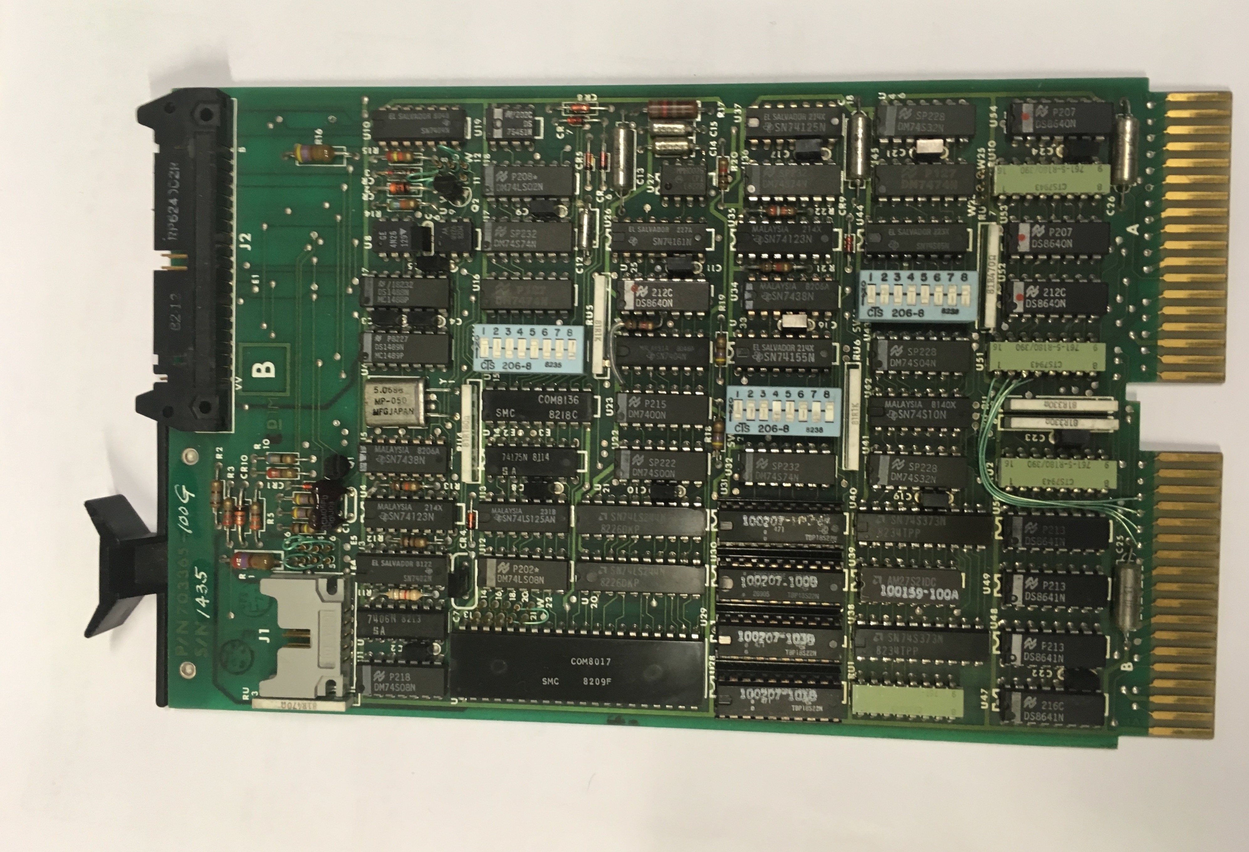
Here you can find the scannned pages I have about the board Plessey Multifunciton Board .
Originally the PCB of this board only had bus termination for 18 address bits. My sample includes an ECO (Engineering Change Order) that connects the additional 4 address bits required for 22-bit addressing to spare PINs of the terminator resistor networks on the card.
I have started to reverse engineer the schematic and create my onw schematic
using EAGLE. Also I disassembled the boot ROMs which supports quite a selection
of devices, but unfortunately no DU:.
There is a 10-Pin header that connects to a front panel. It provides the inputs for a HALT/RUN, POWER-OK and a LTC Enable switch and as well an output which is derived from the SRUN signal from the backplane that connects to the CPU slot which can drive a RUN LED indicator.
Plessey SV-128 Memory
The system was equipped with two SV-128 memory boards, each having 128kw of Memory, so the system had a total of 512kbyte RAM. Pretty good to start with and even enough to boot RSX-11MPlus. Unfortunately one of those two boards failed shortly after reanimating the system. The main reason for my PDP‑11 Q-Bus Memory project. So now the system has 2 or 4 Mbyte of RAM, depending which of my two memory boards I built so far is inserted.

The following scanned pages shows the jumper and DIP switch settings of the Plessey 128kW Memory .
Disk Controller Emulating a RLV12
This is a disk controller that emulates an RLV12 with either 2 or 4 logical units and interfaces to a SASI disk. The original system had a XEBEC S1410 Winchester Disk controller attached to a 20Mbyte Hard disk. The XEBEC S1410 no longer exists but apparently the newest version of the SD2SCSI firmware should support the SASI interface, see the chapter at the end of this article.
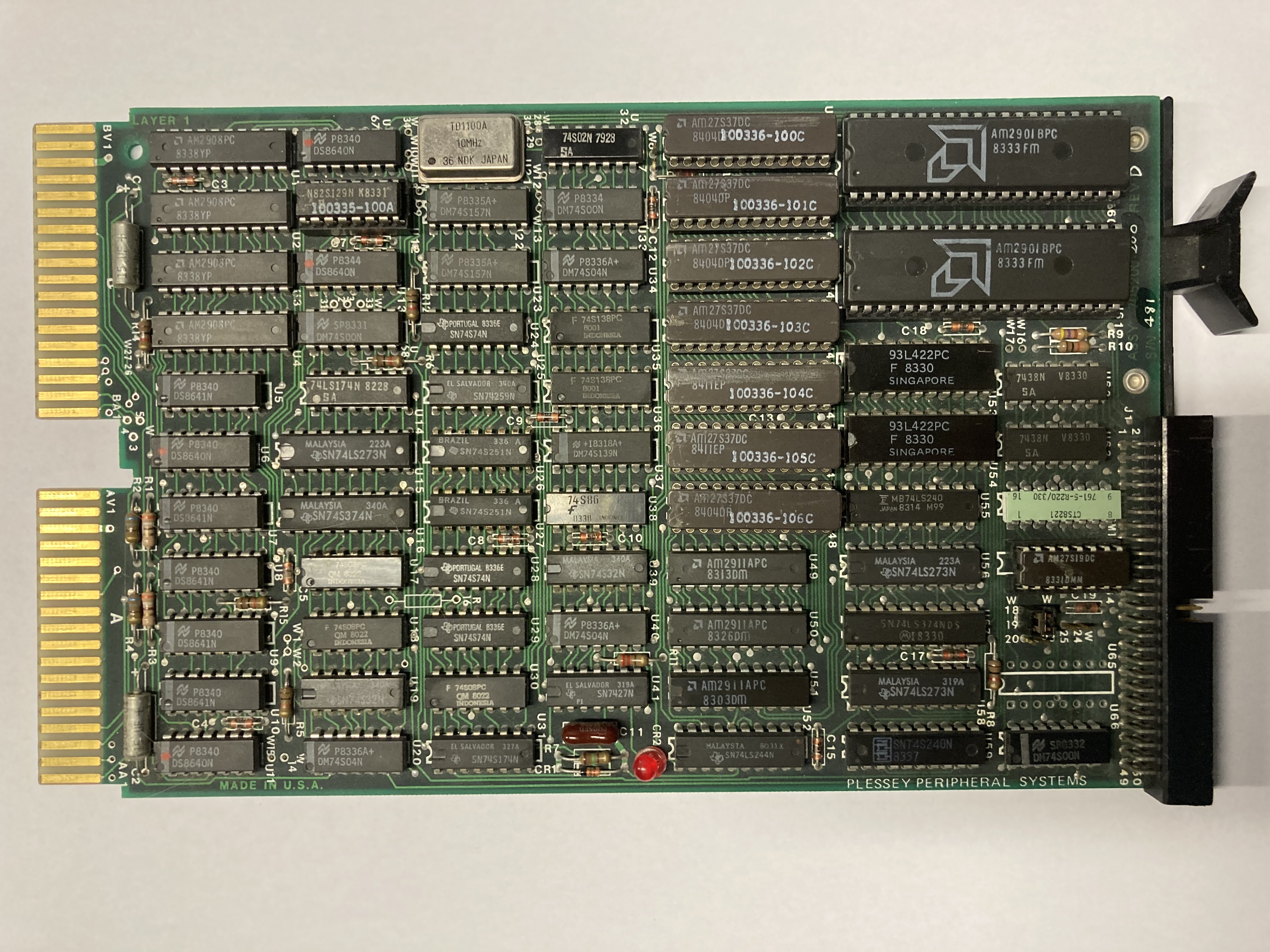
I also have some documentation about a Plessey disk controller that emulates a RLV12, the PM-FCV21B, but in the meantime, when I compare the documentation (jumper settings) with the real hardware, I very much doubt my controller is a PM-FCV21B.
I have some documentation available for the PM-FCV21B but not for my hardware. Plessey Harddisk Controller Documentation
In the meantime I have built my own “RLV12” for the Q-Bus which I use for most of my Q-Bus systems.
Recently I checked the layout and the jumpers with the documentation of the Sigma SDC-RLV12 Controller Model MA400250 Rev C, which is available on bitsavers, and they are identical to the controller I have. I suspect that this Plessey controller is just a copy of the Sigma controller.
At the end of this articel you can read how I revived this controller by using a SCSI2SD and now this controller is again in use.
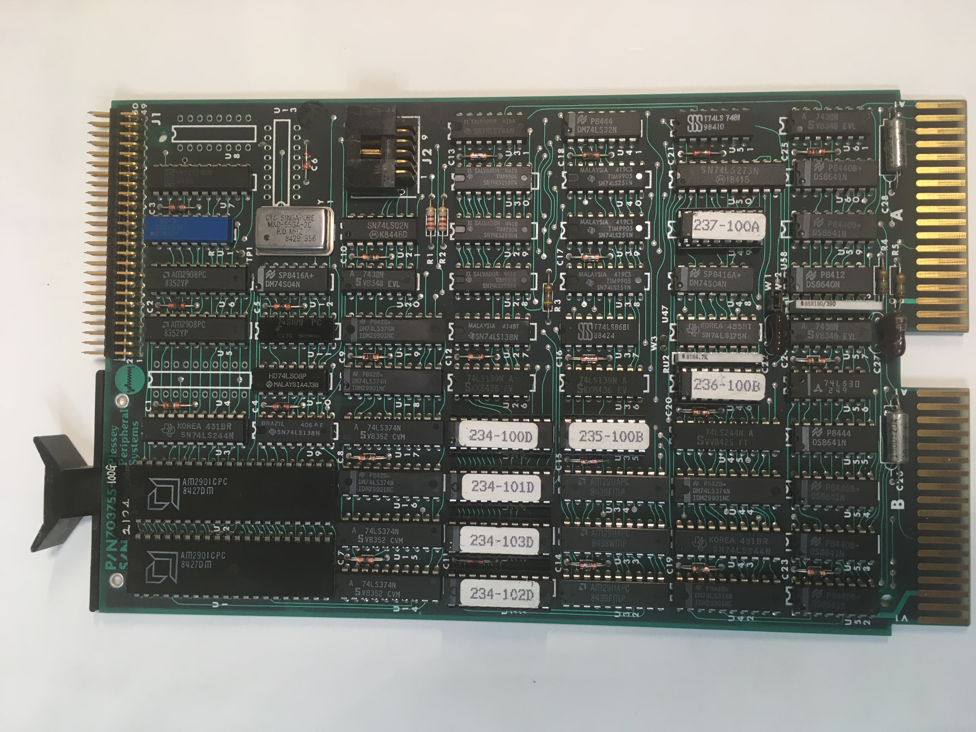
Floppy Controller PM-XCV31
This is a board that emulates a RXV02 but connects to standard Shugart SA800 drives with a standard Shugart Floppy bus. Not yet tested as I don’t have an 8" floppy drives, but I have a PC HD floppy which except for the connector works the same way as an 8" floppy drive and one of my plans is to make an adapter cable and test it. Apparently there was software for it so you could format your floppies but this software is no longer available. So I need to format the floppies with another computer, but that’s another project running.
At least I have some Plessey Floppy Controller Documentation which describes the jumper settings and capabilities.
And here is a picture of the controller
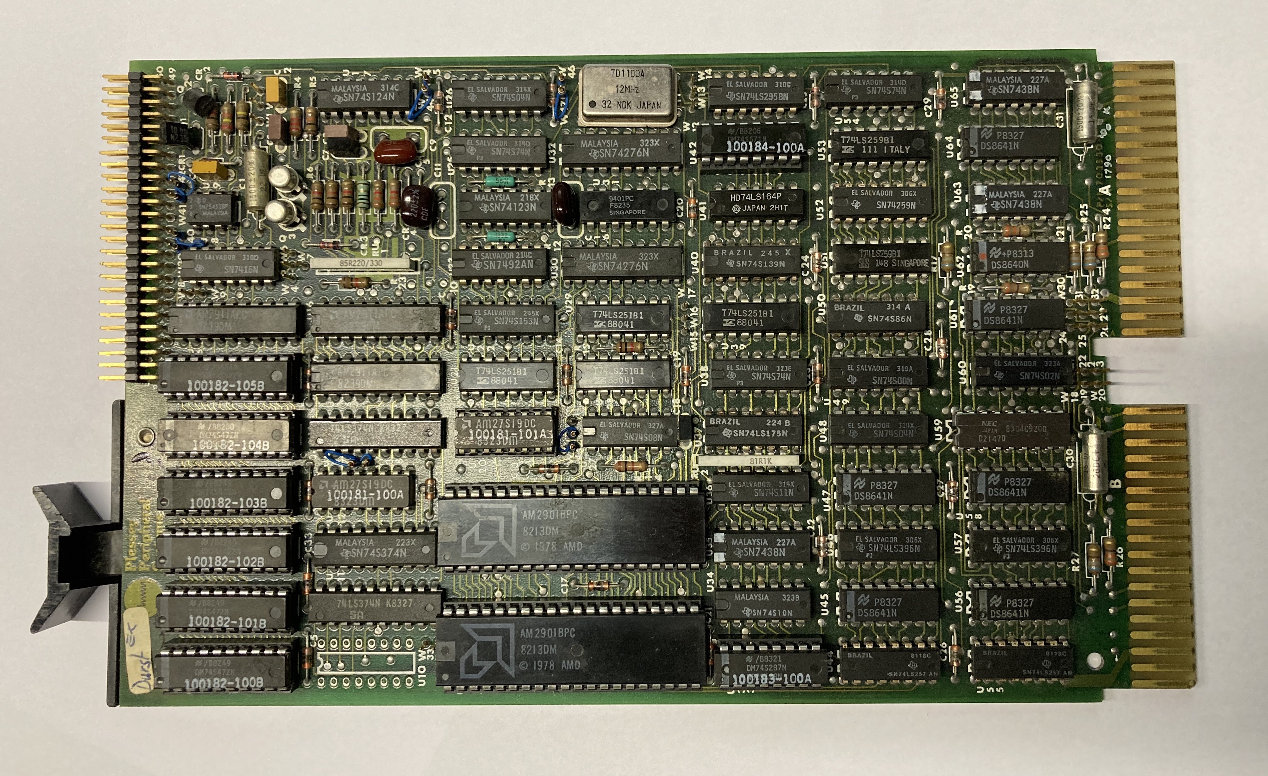
4-Port Serial Adapter PM-DLV11J
As the name indicates this is a clone of the DEC DLV11J M8043, the system also came equipped with two of these cards. The serial interfaces were used to connect to the logistics interfaces and logistics terminals. The system was originally used as a goods verification and registration system of a chemical production plant. So it required a lot of serial interfaces.
In the document linked here you can find information about the DIP switches and the wire-wrap connections of the Plessey DLV11J.
QIC Tape Interface
This is the most mysterious interface card and I have absolutely no information about it, but most probably this is also the card with the least interest.
Plessey Backplane
Another mystery was the backplane and card cage that came with the system. It is a nine slot dual width backplane without bus terminators. It supports 22-bit addressing. There are 4 jumpers that I assume are there to configure the backplane for 18-bit addressing. The system came with 512kbyte which implies that the system was using 22-bit addressing. I do not know for sure what these jumpers are for. They connect to the bus signals BDAL18 to BDAL21, that’s all I know. I have left them as they were. However the layout of the backplane itself is still unique. It requires that a CPU with bus termination is installed in slot 1 and that the Multifunction card is installed in slot 9. Normally in a Q-Bus backplane you must not leave any empty slots between the CPU and the last board, else you need to install signal continuity cards to connect all boards to the interrupt acknowledge and bus grant daisy chain signals. But this particular backplane is wired in a ways so slot 9 is actually directly chained to the interrupt acknowledge signal of the CPU board and then the daisy chain of this slot are brought back to slot 2. In fact a very clever setup as it allows you to leave the console in slot 9 regardless of the configuration. And as both the CPU and the multifunction board inlcude termination the bus was always properly terminated on both ends. For a very long time I did not understand this and because I kept all cards adjacent without a gap. Only by chance I started to populate the system with the CPU in Slot 2 because the air-flow in Slot 1 from the fan in was not sufficient to cool down the CPU board. Suddendly small configurations with all boards adjacent to the CPU board worked.
A second oddity is that the clock input is feed via a dedicated power supply wire to the bus signal named SSPARE2 on slot 9. Another reason why you have to install the Multifunction board in slot 9 as this signal is not bussed. The Multifunction board is provided with input protection on this signal and translates it to the standard Q-Bus levels (provided the LTC register is programmed accordingly)
Power Entry Module
For a long time I used the original DC Power Cable from the high-current connectors of the backplane to a first version of a power entry module. Not only did this first version of the power entry module have many errors but also the DC Power Cable was long and impractical. Therefore I decided to build a new power entry module which was directly attached to the back of the card cage
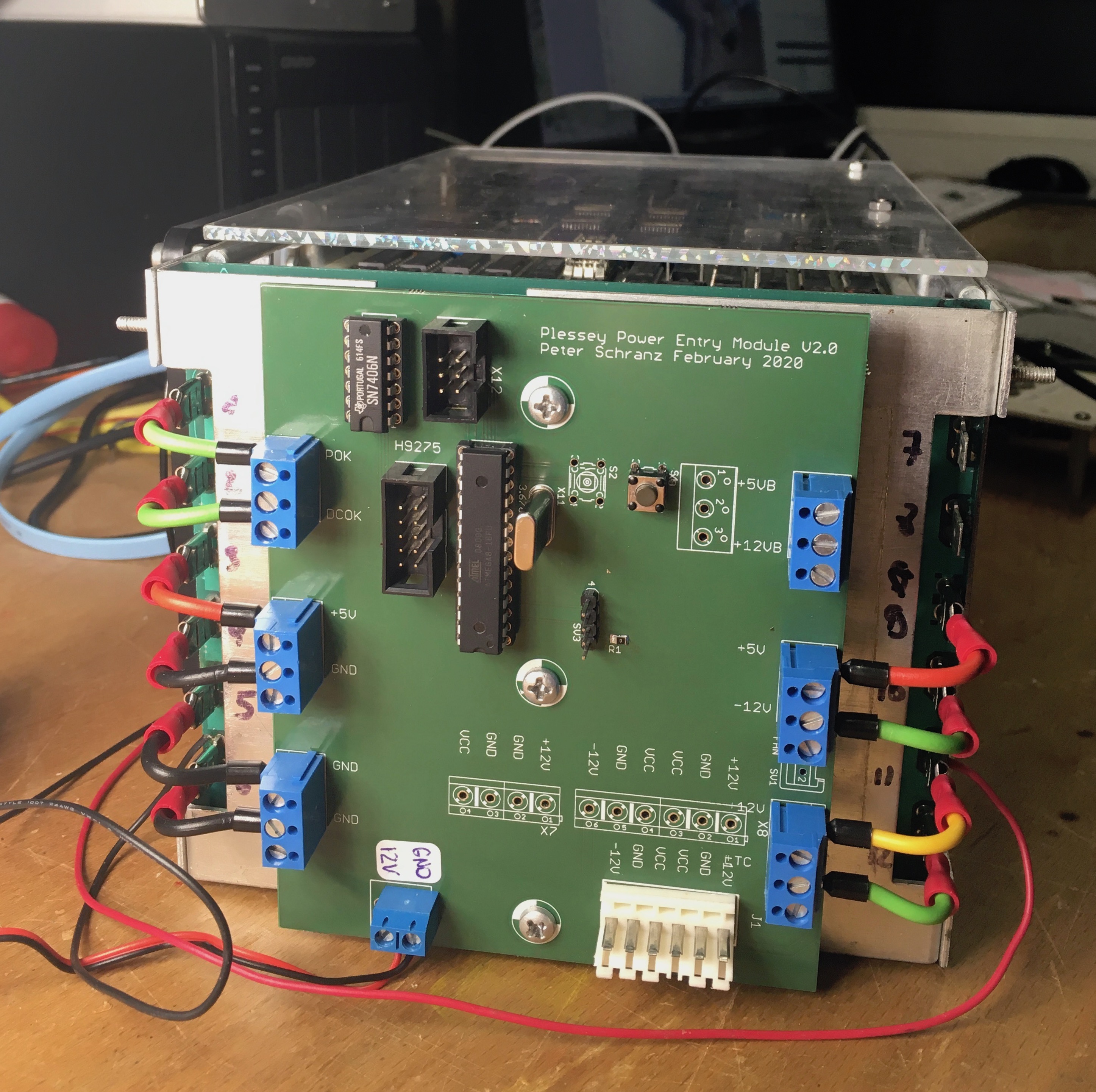
There is an Atmega8 which provides the proper power up sequence for BDCOK and BPOK and as well provides a clock signal to slot 9 via the backplane connector at the bottom right. There are also two buttons which are provided for future expansion as power on reset and halt.
There are two types of power connectors, the first one which is currently soldered in, is used to connect a small Power-Supply I have retrieved from an old Cisco 1841 Router.
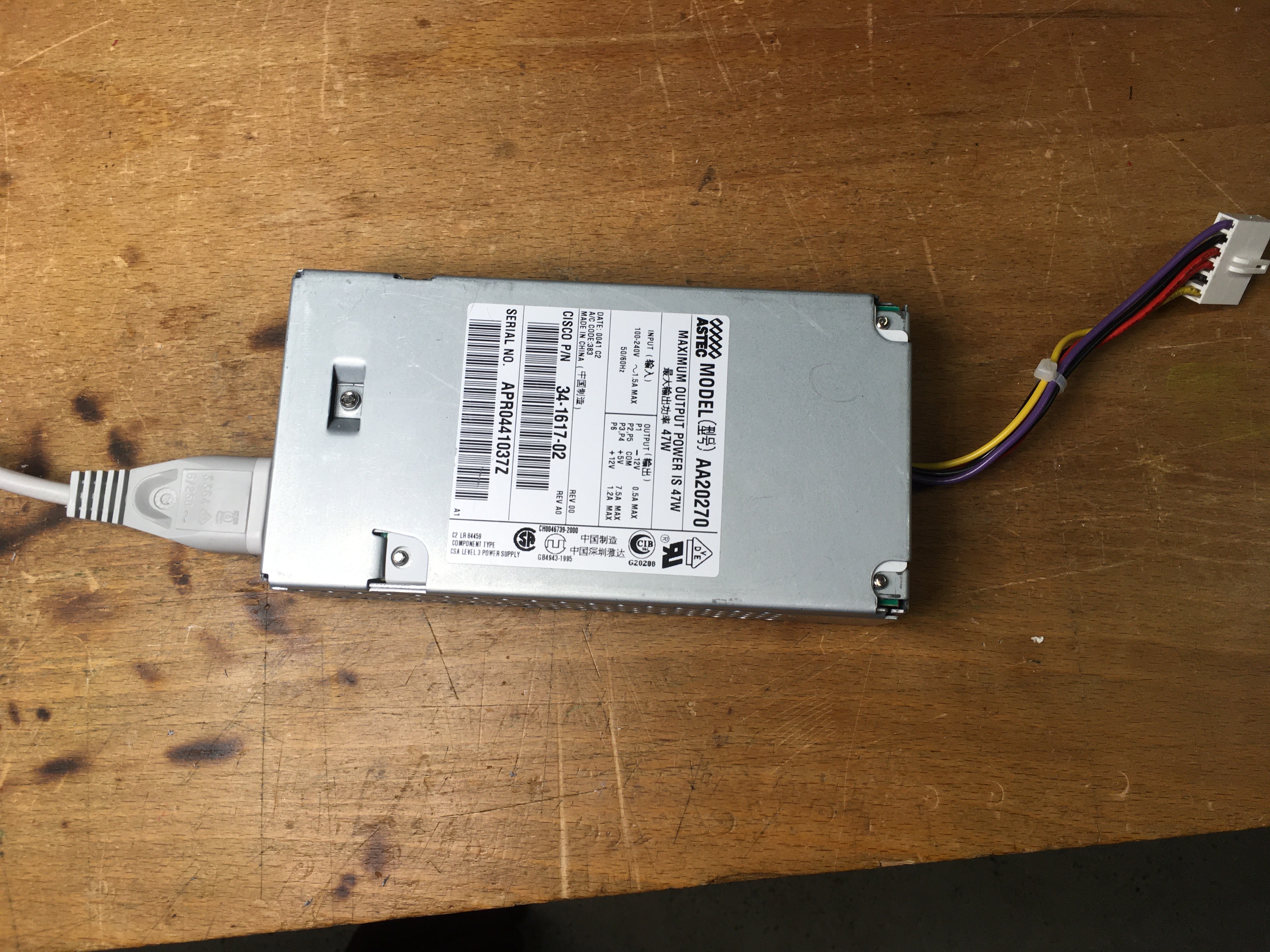
This small PSU just provides enough power for the CPU, the Multifunction Board, one of the Plessey Memory Boards and my RLV12 Emulator to build a minimal system.
There are also screw headers so I can connect a larger PSU if needed. Alternatively to save power I sometimes replace the 256kbyte Plessey Memory with one of my Q-Bus Memory which requires less than 10% of the original memory.
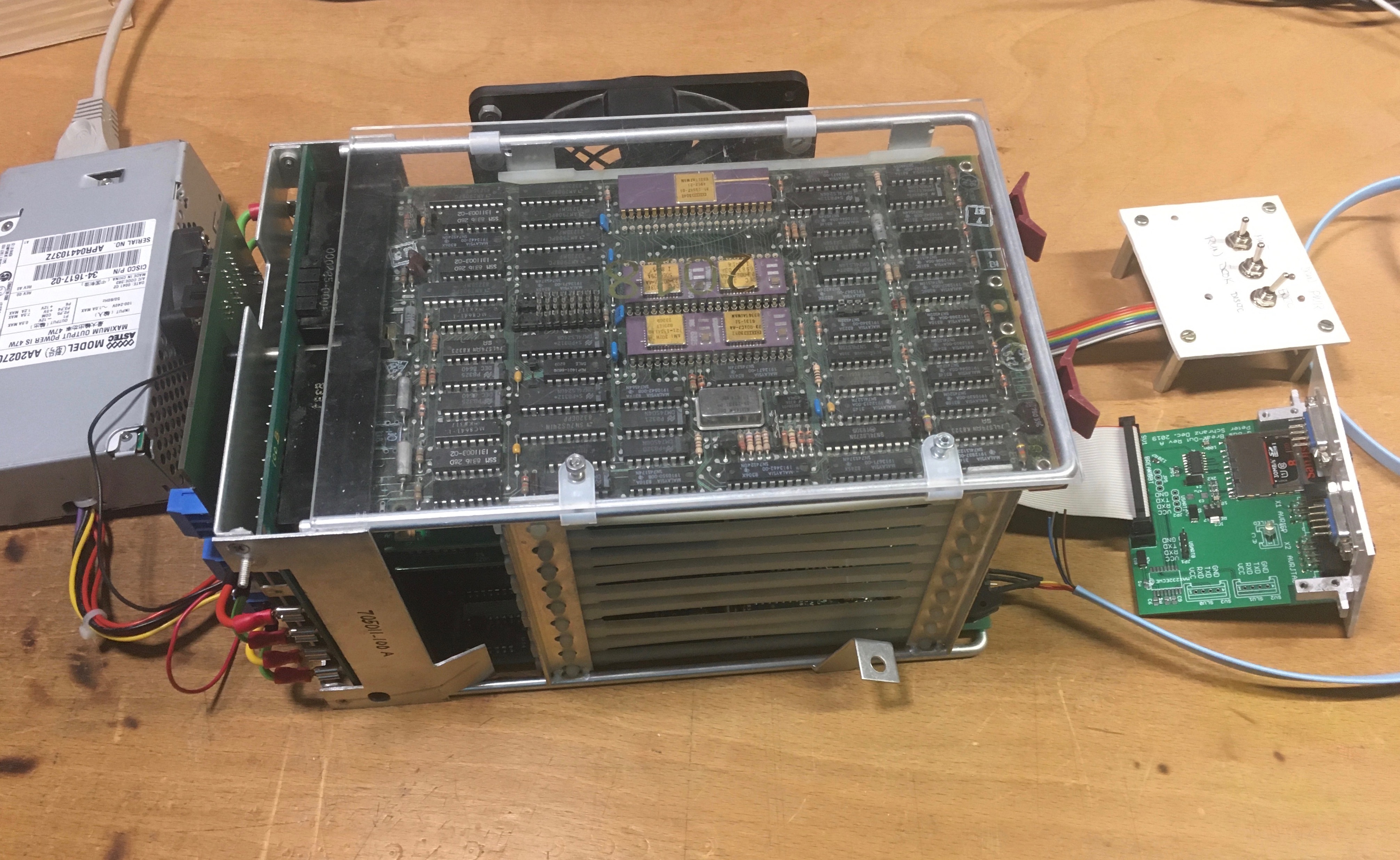
Below you can see a picture of the full setup with power-supply, fans, system, RLV12 break-out and front panel.
Using a SCSI2SD to replace the Xebec S1410
As mentioned, the controller was suspicously similar to the SDC-RLV12 and as I had a spare SCSI2SD V5.0 I gave it a try. The newest firmware 4.8.4 supports SASI and you can configure the SCSI2SD using the scsi-utility to set the behaviour of the SCSI2SD to match a Xebec Winchester Disk Controller.
Note that I had issues with the SCSI2SD V5.1 which I’m still analyzing!
First I removed the configuration PROM, a AM27S19 32x8bit bipolar PROM, and read the values stored in my sample
Address  Data
0x0000   0x91 0x40 0x04 0x00 0x84 0x00 0x00 0x87
0x0008   0x10 0xA0 0x08 0x00 0x84 0x00 0x00 0x07
0x0010   0xD0 0xD6 0x06 0x00 0x84 0x00 0x00 0x04
0x0018   0x90 0xA0 0x08 0x00 0x84 0x00 0x00 0x04
The content is organized as 4 x 8 bytes. Every 8 byte section describes the characteristics of the MFM disk attached to the Xebec S1410 Winchester Disk Controller. Most bytes are used to inform the Xebec Winchester Disk Controller about the number of tracks, heads, write current and precomponsation tracks. These values are not important when we do not have a real MFM disk and just use a SCSI2SD emulating a generic SASI harddisk. Only the upper 4 bits of the 1st byte are important.
Bits 6&7 define the number of units the controller should emulate
| Bit 7 | Bit 6 | Logical Units |
|---|---|---|
| 0 | 0 | 4 |
| 0 | 1 | 3 |
| 1 | 0 | 2 |
| 1 | 1 | 1 |
Bit 5 must be zero and Bit 4 defines the drive type, 0 = RL01 and 1 = RL02. In other words the 2nd configuration was the one I was going for, 4 x RL02. So I changed the jumper to use the second configuration option. The controller also supports a mixed configuration option where you can have 2 MFM harddrives connected to the Xebec controller and use the first or third configuration for the first disk and the second or forth configuration for the second disk.
The good thing was that when connected and powered up the controller immeadiatly
showed all 4 units online and I could even read blocks from each unit using
ODT writing the appropriate values to the controllers device register. However
something was off. The content was not as expected. There are two things you need
to know. First the SDC-RLV12 controller expects 256bytes sectors, the same size
as the sectors on a real RL01/02. And second even so you can set the sector size
of the SCSI2SD to 256bytes it still maps logical block numbers to SD-Card blocks.
In other words only the first 256bytes of every SD-Card block of 512bytes are used.
Therefore I had to write a small utility that takes a diskimage and converts it
to the desired format. First I used cat to concatenate four RL02 disk images
onto one file and then using my utility to convert and copy this image to the SD-Card.
Peters-Mini:disksrsx peter$ cat sdcard/rt11v57dl4.dsk rsx11mphack.dsk rt1153distr.dsk rl0.dsk > xebec-4-rl02.dsk
Peters-Mini:disksrsx peter$ ls -l xebec-4-rl02.dsk
-rw-r--r--  1 peter  staff  41943040 Jan 24 14:03 xebec-4-rl02.dsk
Peters-Mini:disksrsx peter$ sudo ./cvtsector -i xebec-4-rl02.dsk -o /dev/disk4s2
Password:
inputfile: xebec-4-rl02.dsk
outputfile: /dev/disk4s2
argv[0]: ./cvtsector
argv[1]: -i
argv[2]: xebec-4-rl02.dsk
argv[3]: -o
argv[4]: /dev/disk4s2
Peters-Mini:disksrsx peter$
And this is all which is required and as a result I can now boot from the original Plessey disk controller. Here I just load the first block to address 0. Normally you should also set R1 to the CSR value and R2 to the Unit number you loaded the boot block from. But in most cases with RT-11 this works without
@rs/000000 340
@17774400/000201
17774402/000000
17774404/000000
17774406/000000 177400
17774410/000000
@17774400/000201 14
@0gˇ
RT-11XM  V05.07

.TYPE V5USER.TXT

                                   RT-11 V5.7

    Installation  of  RT-11  Version  5.7 is complete and you are now running
    RT-11 from your system volume.

    Your  system volume is your working volume if you have used the Automatic
    Installation (AI) procedure.  If you  have  installed  RT-11  using  that
    procedure,  Mentec  recommends  you verify the  correct operation of your
    system's software using the VERIFY verification procedure.  You can  only
    perform  VERIFY  on  the  valid target (output) media you used for the AI
    procedure.  Run VERIFY before you run CONFIG.  To run VERIFY,  enter  the
    command:
                                   IND VERIFY

    Mentec  recommends  you  read the file V5NOTE.TXT,  which you can TYPE or
    PRINT.  Also, read the Introduction to RT-11, rewritten for  V5.7,  which
    contains much of the information you need to use RT-11 Version 5.7.


.R MSCPCK

.show device

Device    Status                   CSR     Vector(s)
------    ------                   ---     ---------
  DM      Not installed           177440   210
  DU      Not installed           172150   154
  DW      Not installed           000000
  DX      Not installed           177170   264
  DY      Not installed           177170   264
  DZ      Not installed           000000
  LD      Installed               000000   000
  LP      Not installed           177514   200
  LS      Installed               176500   470 474 300 304
  MM      Not installed           172440   224
  MS      Not installed           172522   224 300
  MT      Not installed           172520   224
  MU      Not installed           174500   260
  NC      Not installed           000000
  NL      Installed               000000   000
  NQ      Not installed           174440   120
  NU      Not installed           174510   120
  PI     -Not installed           000000   000
  RK      Not installed           177400   220
  SL      Installed               000000   000
  SP      Installed               000000   110
  UB     -Not installed           170200   000
  VM      Installed               177572   000
  XC      Not installed           173300   210 214
  XL      Installed               176500   300 304
  DL      Resident                174400   160


.show config

RT-11XM  V05.07
Booted from DL0:RT11XM
22 bit addressing is on

USR     is set NOSWAP
EXIT    is set SWAP
KMON    is set NOIND
RUN     is set NOVBGEXE
MODE    is set NOSJ
TT      is set NOQUIET
ERROR   is set ERROR
SL      is set OFF
EDIT    is set KEX
FORTRAN is set FORTRA
KMON nesting depth is 3

CLI is set DCL, CCL, UCL, NO UCF

PDP 11/73A Processor
1024KB of memory
Floating Point Microcode
Extended Instruction Set (EIS)
Memory Management Unit
Parity Memory
Cache Memory
60 Hertz System Clock

Device I/O time-out support
System job support
FPU support


.
Further it also boots into RSX-11M-PLUS
.boot dl1:/for


RSX-11M-PLUS V4.6  BL87   512.KW  System:"HACK11"
>RED DL1:=SY:
>RED DL1:=LB:
>RED DL1:=SP:
>MOU DL1:"HACK11"
>@DL1:[1,2]STARTUP
>;                      PLEASE NOTE
>;
>;      If you have not yet read the system release notes, please do so
>;      now before attempting to perform a SYSGEN or to utilize the new
>;      features of this system.
>;
>;
SET -- Inquire cannot determine terminal type
>;
>; Please ignore any random characters that may have printed on your
>; terminal just now.  They came from a SET /INQUIRE=TI: command.
>; Evidently your terminal does not recognize escape sequences.
>; This will not affect the running of this command file.
>;
>* Please enter time and date (HH:MM DD-MMM-YYYY) [S]: 15:26 29-jan-2021
>TIME 15:26 29-jan-2021
>ACS SY:/BLKS=1024.
>CON ONLINE ALL
>ELI /LOG/LIM
>CLI /INIT=DCL/CTRLC/DPR="<15><12>/$ /"
>INS LB:[1,1]RMSRESAB.TSK/RON=YES/PAR=GEN
>INS LB:[1,1]RMSLBL.TSK/RON=YES/PAR=GEN
>INS LB:[1,1]RMSLBM.TSK/RON=YES/PAR=GEN
>INS $QMGCLI
>INS $QMGCLI/TASK=...PRI
>INS $QMGCLI/TASK=...SUB
>QUE /START:QMG
>INS $QMGPRT/TASK=PRT.../SLV=NO
>QUE LP0:/CR/NM
>START/ACCOUNTING
>CON ESTAT LP0:
>QUE BAP0:/BATCH
>QUE BAP0:/AS:BATCH
>@ <EOF>
>
Diskimage Conversion Utility
Here you have the small utility I hacked. I’m not very experienced in C programming and therefore I just used copy&paste from samples on the internet to build this uitility.
#include <stdio.h>
#include <stdlib.h>
#include <unistd.h>
#include <string.h>

/*
	Peter Schranz	2021-01-28

	In order to use the SCSI2SD to replace a XEBEC S1410
	connected to a SBC-RLV12 we need to convert diskimages
	as the SBC-RVL12 assumes 256bytes sectors. SCSI2SD
	supports 256bytes sectors however each sector is placed
	at the first half of a SD-Card block of 512bytes.

	This program takes a disk-image and writes a new disk
	image where each 512byte block consists of 256bytes from
	the input disk-image
 */
int main(int argc, char **argv)
{

	char ifile[100];
	char ofile[100];
	char buffer[512];
    int opt;
    FILE *ifp, *ofp;

	memset(ifile, '\0', sizeof(ifile));
	memset(ofile, '\0', sizeof(ofile));
	memset(buffer, '\0', sizeof(buffer));

    // put ':' in the starting of the
    // string so that program can
    //distinguish between '?' and ':'
    while((opt = getopt(argc, argv, "i:o:")) != -1)
    {
        switch(opt)
        {
            case 'i':
                printf("inputfile: %s\n", optarg);
                strcpy(ifile, optarg);
                break;
            case 'o':
                printf("outputfile: %s\n", optarg);
                strcpy(ofile, optarg);
                break;
            case ':':
                printf("option needs a value\n");
                break;
            case '?':
                printf("unknown option: %c\n", optopt);
                break;
        }
	}
		for (int i = 0; i < argc; ++i)
	{
		printf("argv[%d]: %s\n", i, argv[i]);
	}


	ifp = fopen(ifile, "rb");

	if(ifp == NULL)
	{
    	perror("Error while opening the input file.\n");
		exit(EXIT_FAILURE);
	}

	ofp = fopen(ofile, "wb");

	if(ofp == NULL)
	{
    	perror("Error while opening the output file.\n");
		exit(EXIT_FAILURE);
	}

	while(fread(buffer, 256, 1, ifp))
	{
		fwrite(buffer, sizeof(buffer), 1, ofp);
	}

	return 0;
}
Controller Boot Function
Reading further in the manual for the SDC-RLV12 it seems this controller has a built-in boot function which comes very handy if there is no bootrom.
@17774416gˇ
RT-11XM  V05.07

.TYPE V5USER.TXT

                                   RT-11 V5.7

    Installation  of  RT-11  Version  5.7 is complete and you are now running
    RT-11 from your system volume.

    Your  system volume is your working volume if you have used the Automatic
    Installation (AI) procedure.  If you  have  installed  RT-11  using  that
    procedure,  Mentec  recommends  you verify the  correct operation of your
    system's software using the VERIFY verification procedure.  You can  only
    perform  VERIFY  on  the  valid target (output) media you used for the AI
    procedure.  Run VERIFY before you run CONFIG.  To run VERIFY,  enter  the
    command:
                                   IND VERIFY

    Mentec  recommends  you  read the file V5NOTE.TXT,  which you can TYPE or
    PRINT.  Also, read the Introduction to RT-11, rewritten for  V5.7,  which
    contains much of the information you need to use RT-11 Version 5.7.


.R MSCPCK

.
In addition to the boot function using the device register 174416(8), which is unused by DEC controllers, the controller also has some sort of built-in boot ROM at address 173000 which can be activated, for this you need to install jumper W6-W7 and the CPU must be jumpered to boot from address 173000.
@177773000/005001
17773002/005007
17773004/005007
17773006/000000
17773010/?
@?
In fact nothing more than the instructions
	clr	R1
	clr	PC
	clr	PC
	halt
I also tested this option and indeed at power up the system now directly boots from DL0:. This is especially useful in my minimal system that consist of the CPU, one memory card, a DLV11J configured to provide the console and this controller.
I’m not sure which trick the controller uses with only these few instructions to load the first two sectors of unit 0 (i.e. 2 x 256bytes) to memory address 0. The only thing the CPU will do is clear the content of R1, I assume to indicate unit 0, and then clears the programm counter, a trick often used to jump to address 0.
Explanation of Boot (update June, 11th 2021)
As it seems the trick behind the above instruction sequence is quite fancy.
The moment the first address, 173000(8), is requested the
controller will present the instruction code for CLR R1, 50018
and at the same time asserts DMR. The next cycle is a DMA cycle. The
controller which will then via DMA place the instruction code for BR . a branch to
iself, 7778, at absolute address 0. Then the controller will
release the bus and the CPU will continue and fetch the next address and
receive the instruction code for CLR PC, 50078. The CPU will
therefore clear the PC and execute the instruction at 0 which is a branch to
itself and will stay in this loop until the controller has retrieved the boot
block and placed it via DMA to the lower memory, making sure that the last
word written is a NOP, 2408, at address 0. Which is how boot
blocks typically start. The rest is the normal boot process, executing the
boot block placed at address 0.