MFM Reader
Project Background
I still have some floppy drives laying around and I always planned to integrated them into my new SBC projects. In the 1990s I had once built a floppy disk controller for an Apple II and also built a SBC around a 65SC816 processor with a floppy disk controller using WD2797 FDC chips. Both worked quite will. FDCs are now obsolete and so I thought about emulating a FDC using a microcontroller. I also could have used new old stock controllers but that was not my intention.
In the internet you find several discussions about this topic and in many cases the conclusion was that it is not possible to read floppies without a controller. However there are also some projects describing a floppy disk emulator using a microcontroller with no or only little additional, external hardware support. Also there are several projects that read the raw MFM data and send it to a PC to decode the data. I was really tempted to give it a try.
My goal was to read and write HD floppies without any additional hardware and be able to read and write the content of individual sectors.
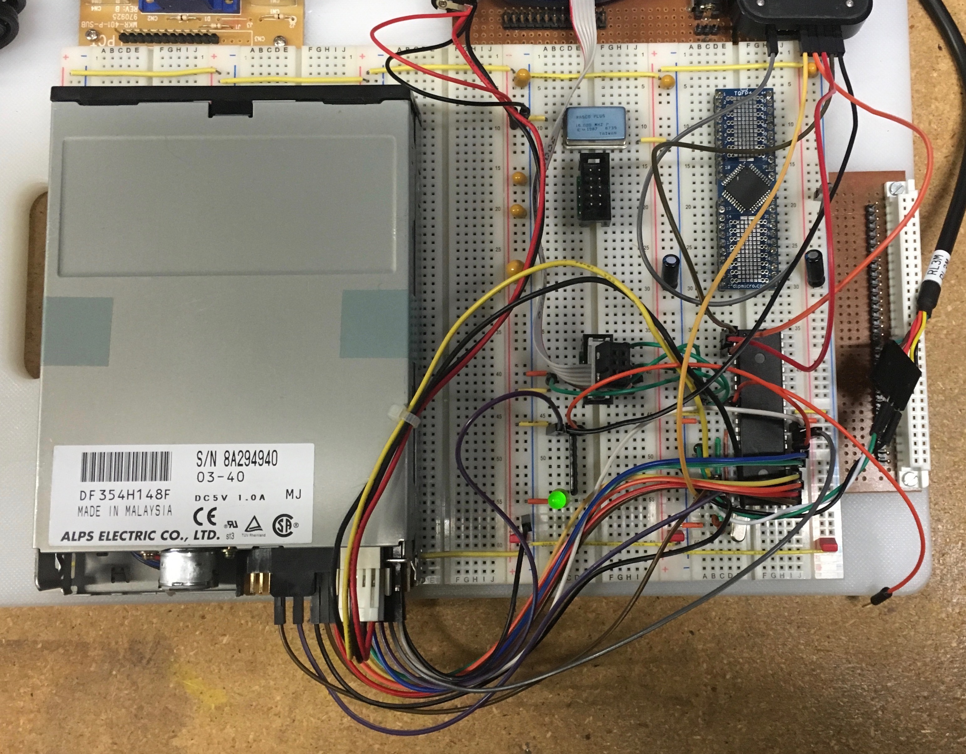
The first project has been realized using an AVR Atmega1284P microcontroller only. Later I added a ATF1504 CPLD to offload the encoding and decoding of MFM. The programming language used for the AVR microcontroller is the standard assembler from AVR Studio 4 and the programming language used for the CPLD is CUPL from the WinCUPL environment form Atmel.
Here is a picture of my test setup using only the microcontroller
How does MFM work
For this project I wanted to fully understand all aspects of MFM and floppy disk formats. So far I understood enough to build floppy controllers using a FDC chip, write device drivers and a formatter and some aspects of MFM. But that was clearly not enough.
You find a lot information how encoding of MFM works. You can read about
clock and data bits and you can read about the A1 SYNC pattern. But
how do you decode it and how do you find and identify this SYNC pattern,
how do you really separate clock and data pulses and how do you
reconstruct the data out of these pulses? I did not find too much
information that could immediately be translated to a solution. In
general they all refer to solutions that require a PLL which
synchronizes to the data rate and then samples the read signal. But the
tiny details are not really described. So I took my own approach and
here is my way to how I managed to read and write floppies.
Data and MFM pattern
When you write data to a magnetic media you need to encode the user data in order to be able to retrieve it. There are many possible ways to do so. I assume that you are familiar with the basics and will only describe the case of standard PC floppy formats using MFM as the encoding format of the bitstream and sectors to write user data.
When writing data to the floppy MFM uses an encoding scheme which first
virtually interleaves data and clock bits. It’s like you interleave the bits of
an arbitrary data byte with a byte that has all bits set, i.e. 0xFF. Let’s assume
we want to encode the byte with the value of 0x3A
data	0x3A	0   0   1   1   1   0   1   0
clock	0xFF	  1   1   1   1   1   1   1   1
Interleaved	0 1 0 1 1 1 1 1 1 1 0 1 1 1 0 1
The rule is that for every 1 in the interleaved data you change the flux on
media. So you avoid having no flux changes when you need to transmit a long data
stream of 0bits. This is because you need regular flux changes when reading
the data to be able to synchronize to the transmission rate, which might
slightly vary or change depending on the rotational speed and speed variations
of a floppy. In fact this is something you need whenever you want to transmit
data serially without a common clock. So to speak everywhere when you record
data on magnetic media or data networks.
The result of the above is what is effectively called FM (frequency modulation).
data	0x3A	0   0   1   1   1   0   1   0
clock	0xFF	  1   1   1   1   1   1   1   1
FM stream	0 1 0 1 1 1 1 1 1 1 0 1 1 1 0 1
MFM now takes a different approach. Instead of writing a flux change for each 1
bit we only create a flux changes when the data bit is 1 or when the clock bit
is between 0 data bits.
data	0x3A	0   0   1   1   1   0   1   0
clock	0xFF	  1   1   1   1   1   1   1   1
MFM stream	0 1 0 0 1 0 1 0 1 0 0 0 1 0 0 ?
The last bit of the MFM stream in the above example will depend on the first bit of the next byte so we cannot tell the value yet. What we immediately see is that compared to FM we have much less flux changes and compared to FM every second flux change has been suppressed. Or in other words we could transmit twice as much data with the same flux change rate used by FM. The rule for MFM is that a clock bit is only generated if the previous and the next data bit are zero. This is also known as a NOR. This is the MFM default rule for flux generations for clock bits.
Decoding
So now we know how to record the data. In the case of MFM flux changes will occur at three well defined intervals. When reading the media every flux change will create a short pulse on the read data line. The intervals between these pulses correspond either to one, one and a half or two times the data bit rate. When you read the floppy this is exactly what you see. MFM makes sure that flux changes are not apart for more than 2 bit intervals. This is somehow the master rule of MFM. And when you look at the read data line you get something like this:
MFM stream 0 1 0 0 1 0 1 0 1 0 0 0 1 0 0 ?
That’s nice but which bit is now the clock and which bit is now the data bit? Fact is you can’t tell from the information we have so far and from this recorded data. The “Internet” tells you that you have now to synchronize to the data rate and extract the clock. But how?
Synchronization
Before we answer this question we need to know that MFM has defined a way
of writing a synchronization pattern. The basis for the synchronization
pattern is a data byte of 0xA1.
data	0xA1	1   0   1   0   0   0   0   1
clock	0xFF	  1   1   1   1   1   1   1   1
MFM stream	1 0 0 0 1 0 0 1 0 1 0 1 0 0 1 ?
Now you take this pattern and remove a flux change without violating the MFM master rule. That is you still have only valid flux change intervals.
data	0xA1	1   0   1   0   0   0   0   1
clock	0xFF	  1   1   1   1   1   1   1   1
MFM stream	1 0 0 0 1 0 0 1 0 1 0 1 0 0 1 ?
MFM sync	1 0 0 0 1 0 0 1 0 0 0 1 0 0 1 ?
		                  *
You skip the flux change at the position marked with a *. This does
not violate the MFM encoding rule and you can show that this is a flux
interval pattern that cannot result from the normal encoding rule (NOR
rule). Now we only need to recognize this pattern. First let’s make some
definitions. As we have seen MFM writes flux changes at certain
intervals. There are three intervals defined. Lets call the intervals
short (S), medium(M) and long(L). Note that the classification of the
interval works for all data rates.
In order to find this pattern we need to read the flux change intervals, this would result in something like:
data	0x3A	0   0   1   1   1   0   1   0
clock	0xFF	  1   1   1   1   1   1   1   1
MFM stream	0 1 0 0 1 0 1 0 1 0 0 0 1 0 0 ?
Intervals	     M    S   S     L       ?

data	0xA1	1   0   1   0   0   0   0   1
clock	0xFF	  1   1   1   1   1   1   1   1
MFM stream	1 0 0 0 1 0 0 1 0 1 0 1 0 0 1 ?
intervals	    L      M    S   S    M    ?
When we do this for the sync pattern we will get something like:
data	0xA1	1   0   1   0   0   0   0   1
clock	0xFF	  1   1   1   1   1   1   1   1
MFM sync	1 0 0 0 1 0 0 1 0 0 0 1 0 0 1 ?
		    L      M      L      M    ?
And that is the clue or the key to synchronization. The interval length
pattern LMLM is unique and you can always say that the flux change ending the
LMLM interval length pattern is a data bit with the value of 1. In fact it is
the last bit of the 0xA1 sync mark.
From that moment on you can just continue to measure the intervals and reconstruct the data that was recorded, because you are now synchronized and know which read pulse is a clock or a data bit.
Floppy Disk Format
The following assumes a normal 3 1/2 inch HD floppy format. But in general it is applicable to all MFM formatted media. First we need to know that the data written to a floppy has a certain structure. Information is written on either side of a disk in tracks. To access a track the read/write head must be placed over the correct track and the correct side must be selected.
In order to be able to retrieve data the user data is written in blocks. Each block of user data is prepended with a header and followed by a trailer. These are called data record or sector. To be able to retrieve the correct sector each sector is preceded with an address record. The address record uses almost the same header and trailer as a data sector.
The header in our case consists of 12 sync bytes, 3 sync marks and the record identification mark.
This sounds pretty sophisticated but its just twelve zero bytes 0x00 encoded
using standard MFM encoding rules, followed by three 0xA1 bytes encoded using
the MFM rule to write sync marks (i.e. with the missing clock bit) and a
identification byte encoded with the standard MFM rules with the value of 0xFE
or 0xFB which tells us if the record is an address or data record
respectively.
Then either the address information or the user data block is written. This is then followed by a CRC-16 written as two bytes. Everything is written using the normal MFM encoding rule.
Then a trailer is written, called GAP, which is nothing more then a bunch of
0x4E data bytes. The GAP after the address record was required to give the
floppy controller some time to analyze and verify the address record and switch
to write mode in case a data sector was written. The GAP after the data record
was used to compensate for small differences of the position and length when a
new data record was written. Both gaps compensated for the fact that you cannot
write a data record at exactly the same position as the existing record.
When later writing a single sector, writing starts with the sync bytes and after
the CRC only two to four bytes of gap data were written as write splice.
The header with twelve 0x00 bytes and the full GAP with with 0x4E bytes
is only written when a floppy is formatted. Over the time parts of these fields
may be smudged a little but the start zeros and the end pattern stay pretty much
the same even when sectors written are not at the exact bit position each time.
So in general a track is just a sequence of address and data record pairs. the address records are written once when the floppy is formatted and contain the sector address of the immediately following data record. Each record is written so it can be retrieved independantly.
There are other aspects regarding the format of a floppy disk, like index pulse, but they are not relevant for this project. For more information regarding the details of a floppy format you will find a lot of information in the internet.
Measure the interval Lengths
Reading the MFM data can be done either using an analogue PLL that synchs to
the starting zeros and then synchronuously decodes the data bits. It is assumed
that the length of the zeroes field is enough to create a stable and correct frequency
during the following record. Then the decoder waits for the sync marks to decide
which pulses are data and clock pulses. This is quite simple because once the
frequency is stable the decoder only needs to lock into the last 1 bit of the
sync mark to be in sync with the data bits.
Or you can also use a digital PLL. For this you need an oscillator that runs at a reasonable high speed. Typically for HD MFM a 16MHz crystal is used. But for modern Floppy drives with stable rotational speed a 8MHz crystal is sufficient. A digital PLL does not synchronise its frequency it just looks for sync marks. To compensate for deviation in the frequency of the MFM and clock the DPLL is implemented as a state machine that can skip a state if the MFM is one clock ahead or add a state if the MFM is one clock behind. This is what I have done with the CPLD.
Another solution emulates the DPLL in software. For this you just need a MCU that executes instructions sychronuous to the CPU clock and supports a CPU clock that is high enough to emulate all states in software. This is what is described below.
In order to read and decode data, the only thing we need to do is measure the
interval lengths and decode them. In my project I use the 8‐bit Timer 0 in
free running mode. The CPU clock is defined via F_CPU and two constants
t_long and t_short are defined as follows:
.equ	F_CPU		= 16000000	; Crystal clock
.equ	t_long	= int(3.5*F_CPU/1000000)
.equ	t_short	= int(2.5*F_CPU/1000000)
	out		TCCR0A, zero
	out		TCCR0B, one
	out		TCNT0, zero
t_long is equivalent to the average of a medium and a long pulse interval and
t_short is the average of a short and a medium pulse interval. When I detect
that the interval is shorter than t_short then I assume it is a short
interval, if it is longer than t_long then I assume it is a long interval and
if it is in between I assume it is a medium interval. I do not really extract
the clock but just adjust myself to fluctuations of the bit rate because I
avoided exact rules for the interval classification. (I use less than, in
between and greater than).
The read signal from the floppy is directly connect to an input pin on Port C. A
macro has been defined that waits for a pulse on RD, reads the timer value and
resets the counter value of Timer 0. We assume that we always enter this
block of code when RD is high, that the RD pulse is long enough so the
sbic instruction can reliably detect a falling edge.
	.macro	btime
	sbis	PINC, RD	; Make sure we begin with RD = High
	inc	miss		; internal missed pulse counter
	sbi	PORTB, 0	; Debugging output
	sbic	PINC, RD	; Wait for a pulse to start
	rjmp	PC-1
	in	temp, TCNT0	; Get Timer value
	out	TCNT0, zero	; Reset Timer for next interval
	cbi	PORTB, 0	; Debugging output
	.endmacro
The temp register has now the number of clock cycles since the last time the
timer has been reset and the timer itself is reset to prepare for the next
read. In the meantime the counter is proceeding we have time to evaluate the
interval length and switch states.
Reading a Record
To read a record we need to first select the drive and in case of a floppy we need to tell the floppy to start the motor that spins the disk. Then we need to place the head above the desired track and select the correct side or head. Now we start to measure the intervals.
First we are looking for the synchronization pattern followed by three sync marks. This is equivalent to a characteristic pattern of interval sizes.
.....SSSSSSSSSSSSSSSSSSSSSSSSSSSSSSSSSSSSSMLMLMSLMLMSLMLM
In theory there should be 96 short intervals as a result from writing the twelve synchronization patterns. But sometimes the first short intervals are not present. So we just look for at least 80 short intervals. This pattern was formerly used to lock and synch the PLL of the data separator. As next we look for the pattern produced by the three sync marks.
The following shows the read routine. It is called readsection as it is used to just read a section of a record. When we start to read the floppy we do not know if the record we find is a data or address record. Therefore this routine is called to read only the number of bytes typically included in an address record. The caller then checks if this is indeed an address record and if the address matches the desired sector. The good thing is that after the address record there is a gap which leaves the microcontroller with a lot of time to perform this check.
If we have found the desired address record we now know that the following record is a data record with the user data. So the program just calls the readsection routine again, but now with the number of bytes set to read a complete data record.
;--------------------------------------------------------------------------
;
;	Read a section from the diskette. First we look for the synchronisation
;	Gap (12 x 0x00) and then check for three SYNC MARKS.
;
;	Y		Buffer Address
;	X		Number of Bytes to Read
;
readsection:

;
;	Read at least 80 consecutive short pulses (normally there are 96
;	pulses from the 12 x 0x00 preamble), we could also read less pulses
;	this has no effect on the sync mark detection, we could as well try
;	to find the sync marks. But I leave them here for nostalgic reasons.
;
;	......SSSSSSSSSSSSSS
;
sstart:
	ldi	count, 80	; less than 12*8
sloop:
	btime
	cpi	temp, t_short
	brsh	sstart		; Not a short pulse
	dec	count
	brne	sloop		; Until we have 80 consecutive short pulses
;
;	Between the consecutive short pulses and the first SYNC MARK we expect
;	a medium pulse
;
;
;		  sync pattern	    sync mark	    sync mark
;	Data	0 0 0 0 0 0 0 0| 1 0 1 0 0 0 0 1| 1 0 1 0 0 0 0 1|
;	Clock	 1 1 1 1 1 1 1 |0 0 0 0 1 1 1 0 |0 0 0 0 1 1 1 0 |
;	MFM	010101010101010|0100010010001001|0100010010001001|
;               	                  ^                ^
;		S S S S S S S (M)   L  M   L   M  S  L   M  L   M
sskip:
	btime
	cpi	temp, t_short
	brlo	sskip		; Another short pulse is ok
	cpi	temp, t_long
	brlo	wlong1		; Yes a medium pulse
	rjmp	sstart		; Not what we expected
;
;	Now we start to find sync marks, there are 3 consecutive SYNC MARKS
;	Sync Marks are the value 0xA1 written with a missing clock pulse without
;	violating the MFM rules regarding the distance between flux changes. This
;	produces the following interval pattern
;
;	....LMLMSLMLMSLMLM
;
;		    sync mark	    sync mark	    sync mark
;	Data	1 0 1 0 0 0 0 1| 1 0 1 0 0 0 0 1| 1 0 1 0 0 0 0 1|
;	Clock	 0 0 0 1 1 1 0 |0 0 0 0 1 1 1 0 |0 0 0 0 1 1 1 0 |
;	MFM	100010010001001|0100010010001001|0100010010001001|
;               	 ^                ^                ^
;	Note missing clock in MFM
;
;	We will only continue as long the pattern of interval matches, else we will
;	start from the beginning (sstart == sync start)
;
wlong1:
	btime			; L
	cpi	temp, t_long
	brlo	wlong11		; not the correct interval start over
;
	btime			; M
	cpi	temp, t_short
	brlo	wlong11		; not the correct interval start over
	cpi	temp, t_long
	brsh	wlong11		; not the correct interval start over
;
	btime			; L
	cpi	temp, t_long
	brlo	wlong11		; not the correct interval start over
;
	btime			; M
	cpi	temp, t_short
	brlo	wlong11		; not the correct interval start over
	cpi	temp, t_long
	brsh	wlong11		; not the correct interval start over
;
	btime			; S
	cpi	temp, t_short
	brlo	wlong2		; got it
;
;	Jump label in case of no match
;
wlong11:
	rjmp	sstart
;
wlong2:
	btime			; L
	cpi	temp, t_long
	brlo	wlong11
;
	btime			; M
	cpi	temp, t_short
	brlo	wlong11
	cpi	temp, t_long
	brsh	wlong11
;
	btime			; L
	cpi	temp, t_long
	brlo	wlong11
;
	btime			; M
	cpi	temp, t_short
	brlo	wlong11
	cpi	temp, t_long
	brsh	wlong11
;
	btime			; S
	cpi	temp, t_short
	brlo	wlong3
;
;	Jump label in case of no match
;
wlong22:
	rjmp	sstart
;
wlong3:
	btime			; L
	cpi	temp, t_long
	brlo	wlong22
;
	btime			; M
	cpi	temp, t_short
	brlo	wlong22
	cpi	temp, t_long
	brsh	wlong22
;
	btime			; L
	cpi	temp, t_long
	brlo	wlong22
;
	btime			; M
	cpi	temp, t_short
	brlo	wlong22
	cpi	temp, t_long
	brsh	wlong22
;
;	We spotted three sync marks now we need to analyze further intervals
;	depending on the current state and the interval size we switch
;	states (l00x0). We collect bits in the register named "char"
;	register "count" is the bitcounter, whenever we have accumulated
;	8 bits we need to store the "char" in the buffer and reload the
;	bitcounter.
;
Now let’s continue with the record read program. First we need another macro:
	.macro	sbyte
;	sbi	PORTB, 2		; Debugging output
	st	Y+, char		; Store byte in buffer
	ldi	count, 8		; Set bitcounter
;	cbi	PORTB, 2		; Debugging output
	sbiw	xh:xl, 1		; Subtract number of bytes to read
	.endmacro
The following piece of code assumes that the Y pointer points to the buffer and the X register contains the number of bytes we want to read. It immediately follows the search record header part (see also duplicated comment). At this point we know that the last pulse was the data pulse of the last bit of the last sync mark. So from now on we can reconstruct the data bits by just looking at the interval length. We will collect the bits using the above macro into bytes. Depending on the current state and the next interval we change to another part of the decoder, it’s like a small state machine. There are at least 2µs between read pulses. In other words the code between states must not use more then 32 cycles. The longest path currently requires 28 cycles.
;
;	Here we are in phase with a "data" pulse
;
l0010:					;
	btime				;  8
	cpi	temp, t_short		;  1
	brsh	l0020			;  2	-> 11
;---------------------------------------------------------
;
;	Short Interval. Next Bit is a '1'
;		--------------->
;	Data	1 0 1 0 0 0 0 1| 1
;	Clock	 0 0 0 1 1 1 0 |0
;	MFM	100010010001001|01
;
	sec				;
	rol	char			; We have a '1'
	dec	count			; We got one more bit
	brne	l0010			; Still more to go
	sbyte				; Save byte, reload bitcounter
					; and decrement number of bytes requested
	brne	l0010			; Need more bytes
	rjmp	readsectiondone		; finished

l0020:
	cpi	temp, t_long		;  1
	brlo	l0040			;  2	-> 14
;---------------------------------------------------------
;
;	Long Interval. Next are two bits '01'
;		--------------->
;	Data	1 0 1 0 0 0 0 1| 0 1
;	Clock	 0 0 0 1 1 1 0 |0 0
;	MFM	100010010001001|0001
;
	lsl	char			;
	dec	count			; we need to check the number of collected
					; bits after every single bit added!
	brne	l0030			;
	sbyte				;
	brne	l0030			;
	rjmp	readsectiondone		;
l0030:
	sec				;
	rol	char			;
	dec	count			;
	brne	l0010			;
	sbyte
	brne	l0010			;
	rjmp	readsectiondone
;---------------------------------------------------------
;
;	Here we are in phase with a "clock" pulse
;
;	last pulse was on a clock and the next data bit is either
;	a zero or a one in which case the next gap is either
;	a short (zero) or a medium(one) a long gap at this
;	stage would be equivalent to a sync mark or a violation
;	violations can occur after the CRC of a data field as
;	writing of data stops right after the CRC and due to
;	various reasons this is not necesserily in sync with
;	the GAP pattern on the diskette.
;
l0060:
	btime
	cpi	temp, t_short
	brlo	l0080
	cpi	temp, t_long
	brsh	l0090
;---------------------------------------------------------
;
;	we have a medium gap and therefore the data bit is a '1'
;	and we are again aligned to the data pulse
;
;		------------------>
;	Data	1 0 1 0 0 0 0 1| 0 0 1
;	Clock	 0 0 0 1 1 1 0 |0 1 0
;	MFM	100010010001001|001001
;
	sec
	rol	char
	dec	count
	brne	l0010
	sbyte
	brne	l0010
	rjmp	readsectiondone
;---------------------------------------------------------
;
;	Here we are in phase with a "data" pulse
;
;	1 1/2 bit cells so we have a clock pulse and next two
;	bits are '00'
;		--------------->
;	Data	1 0 1 0 0 0 0 1| 0 0
;	Clock	 0 0 0 1 1 1 0 |0 1
;	MFM	100010010001001|001
;
l0040:
	lsl	char			;  1
	dec	count			;  1
	brne	l0050			;  2	-> 18
	sbyte
	brne	l0050
	rjmp	readsectiondone
;
l0050:
	lsl	char			;  1
	dec	count			;  1
	brne	l0060			;  1
	sbyte
	brne	l0060			;  2	-> 28
	rjmp	readsectiondone
;---------------------------------------------------------
;
;	Here we are in phase with a "clock" pulse
;
;	we have a short pulse, and therefore the data bit is
;	zero and we are back at the situation where the pulse
;	was on a clock
;
;		------------------>
;	Data	1 0 1 0 0 0 0 1| 0 0 0
;	Clock	 0 0 0 1 1 1 0 |0 1 1
;	MFM	100010010001001|00101
;
l0080:
	lsl	char
	dec	count
	brne	l0060
	sbyte
	brne	l0060
	rjmp	readsectiondone
;---------------------------------------------------------
;
;	Here we are in phase with a "clock" pulse and at the
;	same time we have a long gap, at this stage this is
;	equivalent to a missing clock pulse.
;
;	Note: A long gap can normally not occur with the
;	pulses synced to the clock position. Such a gap
;	would require that the data bit after the first
;	pulse is 0 and at the same time the next data bit
;	which is right before the second pulse as well.
;	But two data bits produce a clock pulse in between
;	which obviously is missing (see X) as such this
;	is considered to be a read error
;
;		------------------>
;	Data	1 0 1 0 0 0 0 1| 0 0 0 0
;	Clock	 0 0 0 1 1 1 0 |0 1 X 1
;	MFM	100010010001001|0010001
;

l0090:
	sec
	ret

readsectiondone:
	clc
	ret
Reading a sector
To read a sector you need to call the readsection routine to read the first 8 bytes of the next record. Make sure it is an address record.
	ldi	yl, low(buffer)	; Buffer
	ldi	yh, high(buffer)

	movw	zh:zl, yh:yl		; Save buffer
readsectors000:
	ldi	xl, low(8)		; Bytes to collect
	ldi	xh, high(8)
	clr	miss
	rcall	readsection		; Read (8 bytes) from next record on floppy
	brcs	readerror005
	ldd	temp, Z+0		; Get first byte
	cpi	temp, 0xFE		; is it an address mark
	breq	readsectors010		; yes found a sector address
readsectors005:
	movw	yh:yl, zh:zl		; Restore buffer, next section is
	rjmp	readsectors000		; most likely an address section

readsectors010:
Now you can check the CRC and then check if it is the correct sector. If everything is ok the next record is supposed to be the data record containing the sector data we were looking for. Just call readsection again now with as many bytes to read as required by the sector length or the exepcted sector length, the following assumes a sector length of 512bytes. However we could set the length according the sector length field of the previously read address section. There is enough time for the corresponding calculation the following gives a table of possible sector lengths
- 0x00 128bytes
- 0x01 256bytes
- 0x02 512bytes
- 0x03 1024bytes
	ldi	yl, low(buffer)	; Buffer
	ldi	yh, high(buffer)

	movw	zh:zl, yh:yl		; Save buffer
	ldi	xl, low(515)		; Bytes to collect
	ldi	xh, high(515)
	clr	miss
	rcall	readsection		; Read (8 bytes) from next record on floppy
You need to read 3 bytes more than the sector size as you also need to read the data mark and the 2 CRC bytes. Note that above we assume a sector length of 512bytes. However the real sector length is encoded in the address header and for a universal read routine you need to set the buffer and the size accordingly.
Here a sample code to convert the sector length to buffer length
	ldd	count, Y+4		; Sector length
	ldi	xl, low(64)
	ldi	xh, high(64)
readsectl:
	lsl	xl
	rol	xh
	dec	count
	brpl	readsectl
	adiw	xh:xl, 3
Now you should have the desired sector in your buffer.
CRC Calculation
There are many methods to calculate the CRC of address and data records. Here I explain my favorite method. This method uses a precalculated look-up table and calculates the CRC byte-wise. This is extremely fast, even on a 8-bit MCU.
Byte-wise calculation of CRC-16 requires a look-up table of 256 16-bit words. As the AVR processors are 8-bit processors I have split the table into two 256-byte tables in order to be able to lookup the low and the high byte using the byte value as the index. I even align the tabels on a 256-byte boundary so I can directly use the byte value as the lower 8-bit’s of the index into the tables.
	align	8
;
;	low byte CRC lookup table
;
crclo:
 .db 0x00,0x21,0x42,0x63,0x84,0xA5,0xC6,0xE7,0x08,0x29,0x4A,0x6B,0x8C,0xAD,0xCE,0xEF
 .db 0x31,0x10,0x73,0x52,0xB5,0x94,0xF7,0xD6,0x39,0x18,0x7B,0x5A,0xBD,0x9C,0xFF,0xDE
 .db 0x62,0x43,0x20,0x01,0xE6,0xC7,0xA4,0x85,0x6A,0x4B,0x28,0x09,0xEE,0xCF,0xAC,0x8D
 .db 0x53,0x72,0x11,0x30,0xD7,0xF6,0x95,0xB4,0x5B,0x7A,0x19,0x38,0xDF,0xFE,0x9D,0xBC
 .db 0xC4,0xE5,0x86,0xA7,0x40,0x61,0x02,0x23,0xCC,0xED,0x8E,0xAF,0x48,0x69,0x0A,0x2B
 .db 0xF5,0xD4,0xB7,0x96,0x71,0x50,0x33,0x12,0xFD,0xDC,0xBF,0x9E,0x79,0x58,0x3B,0x1A
 .db 0xA6,0x87,0xE4,0xC5,0x22,0x03,0x60,0x41,0xAE,0x8F,0xEC,0xCD,0x2A,0x0B,0x68,0x49
 .db 0x97,0xB6,0xD5,0xF4,0x13,0x32,0x51,0x70,0x9F,0xBE,0xDD,0xFC,0x1B,0x3A,0x59,0x78
 .db 0x88,0xA9,0xCA,0xEB,0x0C,0x2D,0x4E,0x6F,0x80,0xA1,0xC2,0xE3,0x04,0x25,0x46,0x67
 .db 0xB9,0x98,0xFB,0xDA,0x3D,0x1C,0x7F,0x5E,0xB1,0x90,0xF3,0xD2,0x35,0x14,0x77,0x56
 .db 0xEA,0xCB,0xA8,0x89,0x6E,0x4F,0x2C,0x0D,0xE2,0xC3,0xA0,0x81,0x66,0x47,0x24,0x05
 .db 0xDB,0xFA,0x99,0xB8,0x5F,0x7E,0x1D,0x3C,0xD3,0xF2,0x91,0xB0,0x57,0x76,0x15,0x34
 .db 0x4C,0x6D,0x0E,0x2F,0xC8,0xE9,0x8A,0xAB,0x44,0x65,0x06,0x27,0xC0,0xE1,0x82,0xA3
 .db 0x7D,0x5C,0x3F,0x1E,0xF9,0xD8,0xBB,0x9A,0x75,0x54,0x37,0x16,0xF1,0xD0,0xB3,0x92
 .db 0x2E,0x0F,0x6C,0x4D,0xAA,0x8B,0xE8,0xC9,0x26,0x07,0x64,0x45,0xA2,0x83,0xE0,0xC1
 .db 0x1F,0x3E,0x5D,0x7C,0x9B,0xBA,0xD9,0xF8,0x17,0x36,0x55,0x74,0x93,0xB2,0xD1,0xF0
;
;	high byte CRC lookup table
;
crchi:
 .db 0x00,0x10,0x20,0x30,0x40,0x50,0x60,0x70,0x81,0x91,0xA1,0xB1,0xC1,0xD1,0xE1,0xF1
 .db 0x12,0x02,0x32,0x22,0x52,0x42,0x72,0x62,0x93,0x83,0xB3,0xA3,0xD3,0xC3,0xF3,0xE3
 .db 0x24,0x34,0x04,0x14,0x64,0x74,0x44,0x54,0xA5,0xB5,0x85,0x95,0xE5,0xF5,0xC5,0xD5
 .db 0x36,0x26,0x16,0x06,0x76,0x66,0x56,0x46,0xB7,0xA7,0x97,0x87,0xF7,0xE7,0xD7,0xC7
 .db 0x48,0x58,0x68,0x78,0x08,0x18,0x28,0x38,0xC9,0xD9,0xE9,0xF9,0x89,0x99,0xA9,0xB9
 .db 0x5A,0x4A,0x7A,0x6A,0x1A,0x0A,0x3A,0x2A,0xDB,0xCB,0xFB,0xEB,0x9B,0x8B,0xBB,0xAB
 .db 0x6C,0x7C,0x4C,0x5C,0x2C,0x3C,0x0C,0x1C,0xED,0xFD,0xCD,0xDD,0xAD,0xBD,0x8D,0x9D
 .db 0x7E,0x6E,0x5E,0x4E,0x3E,0x2E,0x1E,0x0E,0xFF,0xEF,0xDF,0xCF,0xBF,0xAF,0x9F,0x8F
 .db 0x91,0x81,0xB1,0xA1,0xD1,0xC1,0xF1,0xE1,0x10,0x00,0x30,0x20,0x50,0x40,0x70,0x60
 .db 0x83,0x93,0xA3,0xB3,0xC3,0xD3,0xE3,0xF3,0x02,0x12,0x22,0x32,0x42,0x52,0x62,0x72
 .db 0xB5,0xA5,0x95,0x85,0xF5,0xE5,0xD5,0xC5,0x34,0x24,0x14,0x04,0x74,0x64,0x54,0x44
 .db 0xA7,0xB7,0x87,0x97,0xE7,0xF7,0xC7,0xD7,0x26,0x36,0x06,0x16,0x66,0x76,0x46,0x56
 .db 0xD9,0xC9,0xF9,0xE9,0x99,0x89,0xB9,0xA9,0x58,0x48,0x78,0x68,0x18,0x08,0x38,0x28
 .db 0xCB,0xDB,0xEB,0xFB,0x8B,0x9B,0xAB,0xBB,0x4A,0x5A,0x6A,0x7A,0x0A,0x1A,0x2A,0x3A
 .db 0xFD,0xED,0xDD,0xCD,0xBD,0xAD,0x9D,0x8D,0x7C,0x6C,0x5C,0x4C,0x3C,0x2C,0x1C,0x0C
 .db 0xEF,0xFF,0xCF,0xDF,0xAF,0xBF,0x8F,0x9F,0x6E,0x7E,0x4E,0x5E,0x2E,0x3E,0x0E,0x1E
My CRC calculation makes use of a macro which assumes that we have defined two registers.
.def	crcl	= r12				; Used to calculate CRC
.def	crch	= r13				;            "
Next there is a macro which produces in-line code to update the CRC with the next byte
.macro	updcrc
	mov		zl, @0			;  1
	eor		zl, crch		;  1
	ldi		zh, high(2*crchi)	;  1
	lpm		crch, Z			;  3
	eor		crch, crcl		;  1
	dec		zh			;  1
	lpm		crcl, Z			;  3
.endmacro
Calculation of CRC-16 for one byte just takes 11 cycles. In other words on a 16MHz AVR you can calculate at about 1Mbyte/sec. You calculate the CRC of an address or data record as follows. As always you need to initialise the CRC before you can start calculation with data bytes. CRC-16 presets the CRC with 0xFFFF.
	mov	crcl, ff
	mov	crch, ff
	ldi	temp, 0xa1
	updcrc	temp
	ldi	temp, 0xa1
	updcrc	temp
	ldi	temp, 0xa1
	updcrc	temp
	ld	temp, Y+
	updcrc	temp
	.
	.
	.
Note that the three sync marks make part of the CRC. In other word the CRC is calulated using the sync marks, the address or data mark and the data bytes. Of course you need to perform the calculation for all bytes in the record.