RLV12 V2.0 Breakout Board
Motivation
When I was using the first version of the Q-Bus RLV12 emulator it was very soon clear that the connectors for ISP, JTAG, Console and the SD-Card slot were at very sub-optimal, non-accessible places once the card was inserted into a Q-Bus backplane. Therefore the idea was to bring all these interfaces to a break-out board and connect the RLV12 controller and the break-out board with a ribbon cable. However this is not as trivial as it seems as the ISP interface that is used as SPI interface to access the SD-Card at a much higher rate. This makes delay and ringing an issue. Therefore the level shifters/buffers have been moved as well from the controller to the break-out board to have a controlled termination of the lines.
Currently the setup has been tested with a ribbon cable of approx. 50cm (20"). When a longer cable is required the SPI clock rate could be reduced and cable lengths of up to 1m are feasible.
Schematic
The break-out board was designed to not only match the needs of the RLV12 controller but of all controllers I have built so far. Therefore the cable has room for a ISP to programm the MCU, a JTAG interface to program the CPLD(s), the level shifters for the SD-Card interface. It has reseved lines for up to 4 UARTs and it can accomodate RS-232 level shifters in case you want to have standard RS-232 interfaces to control the Q-Bus controller

Note that the break-out board also receives power from the RLV12 emulator.
PCB Layout
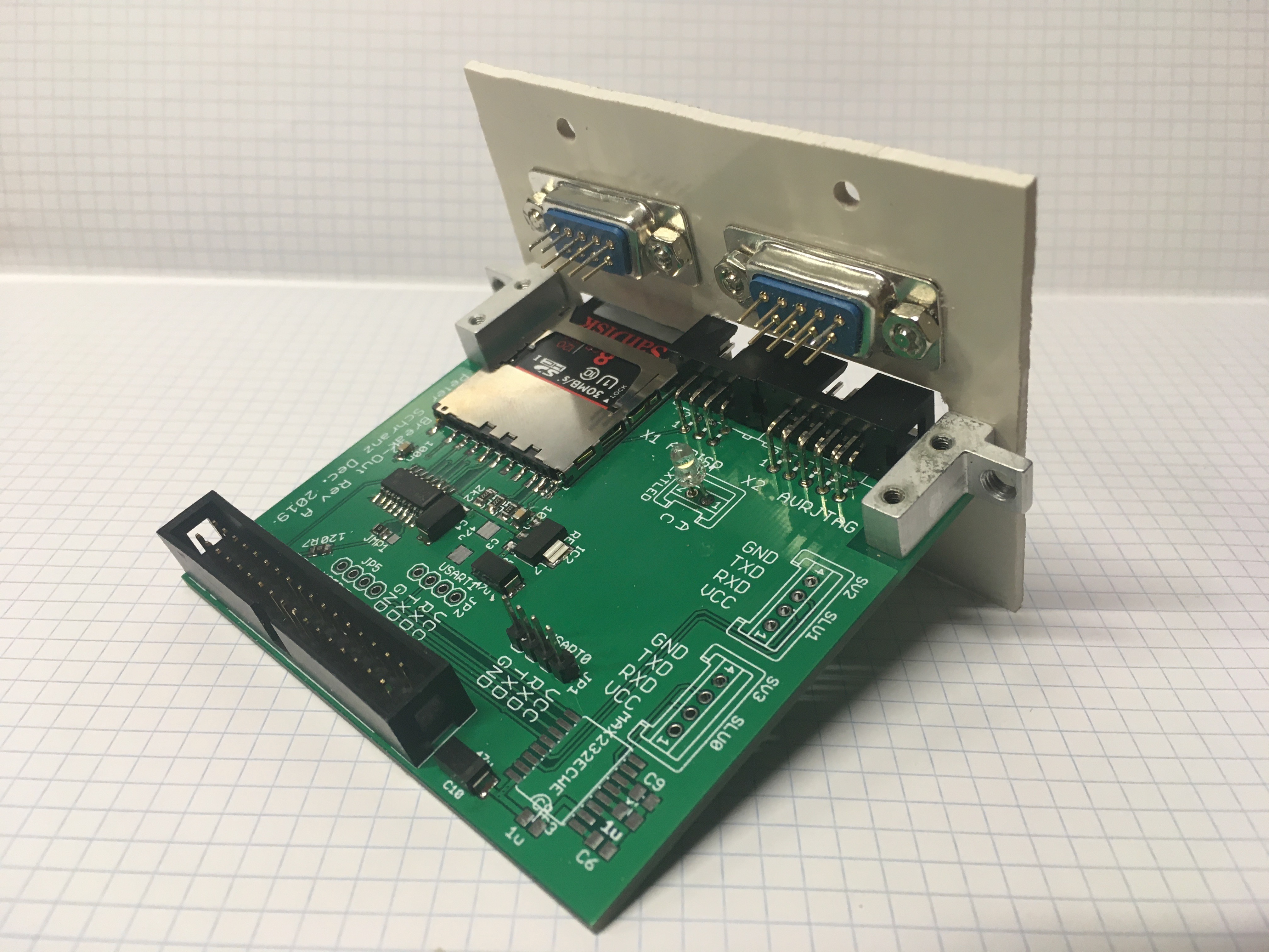
The PCB is small enough so it can be installed attached to a BA23 filler panel. The following shows a mock-up of filler panel in ABS plastic. The PCB shown is a slightly modified version of that shown in the overview. I have added the activity LED. In my case it is mounted directly on the PCB but the idea of course is to drill a whole in the panel and place the LED there. Also I have removed the copper pour from the edges, where the mounting brackets with the screws are placed, to avoid any risk of short circuits in case they are made of metal like mine which are made of aluminium. And I have also corrected the labels of the pins. In my case I have not mounted the MAX232 level shifter and of course no wires are running from the DB-9 connector to the PCB. Note that for the RLV12 Emulator you only need USART0 in case you are using a USB to Serial-TTL cable or SLU0 when installing the MAX232.
First a picture from the rear. I did not yet mount the RS-232 levels shifter and also the wires from the pads on the pcb to the DB-9 connecters are missing.
Note:The 4x1 pin-header is provided to connect a USB-Serial-TTL cable. Make sure your cable has the pin-out as marked on the PCB before you connect it.
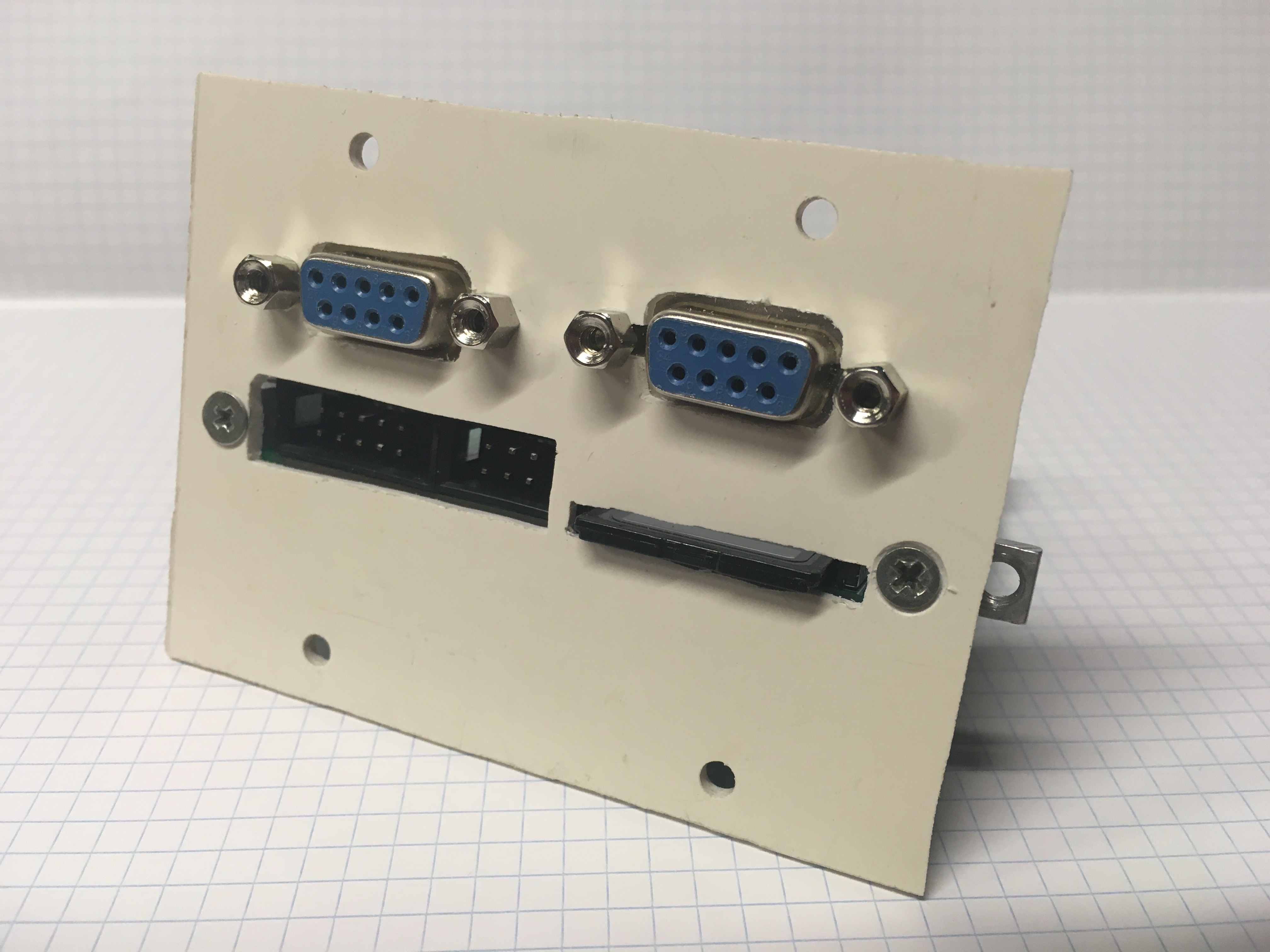
And from the front you can see that now all interfaces are accessible, that is
- ISP to program the MCU
- JTAG to program the CPLDs
- SD-Card slot, this is a push-push slot so you can easily remove the card
- DB-9, one is used to access the control program of the RLV12 emulator the other is not required
Note: in the initial version of the RLV12 Emulator V2.0 there were not enough pins available on the MCU to support an additional activity LED. However when I removed the copy of the CSR register from the main CPLD I had one pin left. In order to activate the activity LED with this break-out board you have to add a small wire to the current PCB of the RLV12 Emulator V2.0. This is described in the building instructions.
BOM - Bill of Materials
The following table gives the BOM of the breakout board.
| Name | Value | Package | Description |
| C1 | 100n | C0805 | Decouplilng Capacitor |
| C2 | 100n | C0805 | Decouplilng Capacitor |
| C3 | 47u | SMC_C | Decouplilng Capacitor |
| C4 | 47u | SMC_C | Decouplilng Capacitor |
| C5 | 47u | SMC_C | Decouplilng Capacitor |
| C6 | 1u | C0805 | RS-232 Level Shifter Pump |
| C7 | 1u | C0805 | RS-232 Level Shifter Pump |
| C8 | 1u | C0805 | RS-232 Level Shifter Pump |
| C9 | 1u | C0805 | RS-232 Level Shifter Pump |
| C10 | 47u | SMC_C | Decouplilng Capacitor |
| D1 | RED | FKIT-LED-1206 | Activity LED |
| IC1 | 74HC4050D | SO16 | Hex High-Voltage Buffer |
| IC2 | REG1117 | SOT223 | LDO Voltage Regulator |
| IC3 | MAX232ECWE | SO16L | RS-232 Level Shifter |
| JMP1 | A0R-JMP | Jumper | |
| JP1 | USART0 | 1X04 | Pin Header |
| JP2 | USART1 | 1X04 | Pin Header |
| JP5 | USER | 1X04 | Pin Header |
| R1 | 2k2 | M0805 | Pull-Up Resistor |
| R2 | 2k2 | M0805 | Pull-Up Resistor |
| R3 | 0Ohm | M0805 | Solder Jumper |
| R4 | 0Ohm | M0805 | Solder Jumper |
| R5 | 0Ohm | M0805 | Solder Jumper |
| R6 | 0Ohm | M0805 | Solder Jumper |
| R7 | 120Ohm | M0805 | Serial Attenuation |
| R8 | 2k2 | M0805 | Pull-Up Resistor |
| R9 | 220Ohm | M0805 | LED Resistor |
| SV1 | BREAKOUT | ML34 | IDC-34 Connector |
| SV2 | SLU1 | S04P | RS-232 Header |
| SV3 | SLU0 | S04P | RS-232 Header |
| SV4 | EXTLED | S02P | External LED |
| U$1 | SDMMC06132 | YAMAICHI-FPS-009-2405-0 | SD-Card Cage |
| X1 | AVRISP | ML6L | IDC-6 Connector Angled |
| X2 | AVRJTAG | ML10L | IDC-10 Connector Angled |
USB to Serial Extension (update June 2020)
Why would you add an RS-232 interface to a new device like the RLV12 Emulators when at the end of the day you need to connect it to a computer that no longer has serial interfaces and therefore requires a USB-to-Serial adapter. So I was thinking about an extension to the Break-Out board that includes a USB-to-Serial chip. I decided to use the FT230X USB to serial chip because it includes a unique serial number. On macOS this serial number is used as part of the device name and allows to easily identify the USB-to-Serial port.
A small PCB has been created that can be attached to the other side of the mounting blocks made in aluminium. Then you add three wires for GND, TX and RX to the main break-out PCB to the corresponding UART. The new PCB includes twice the same logic to interface to up to 2 UARTs. You only need to populate one for the RVL12 Emulator. Here you can see the prototype
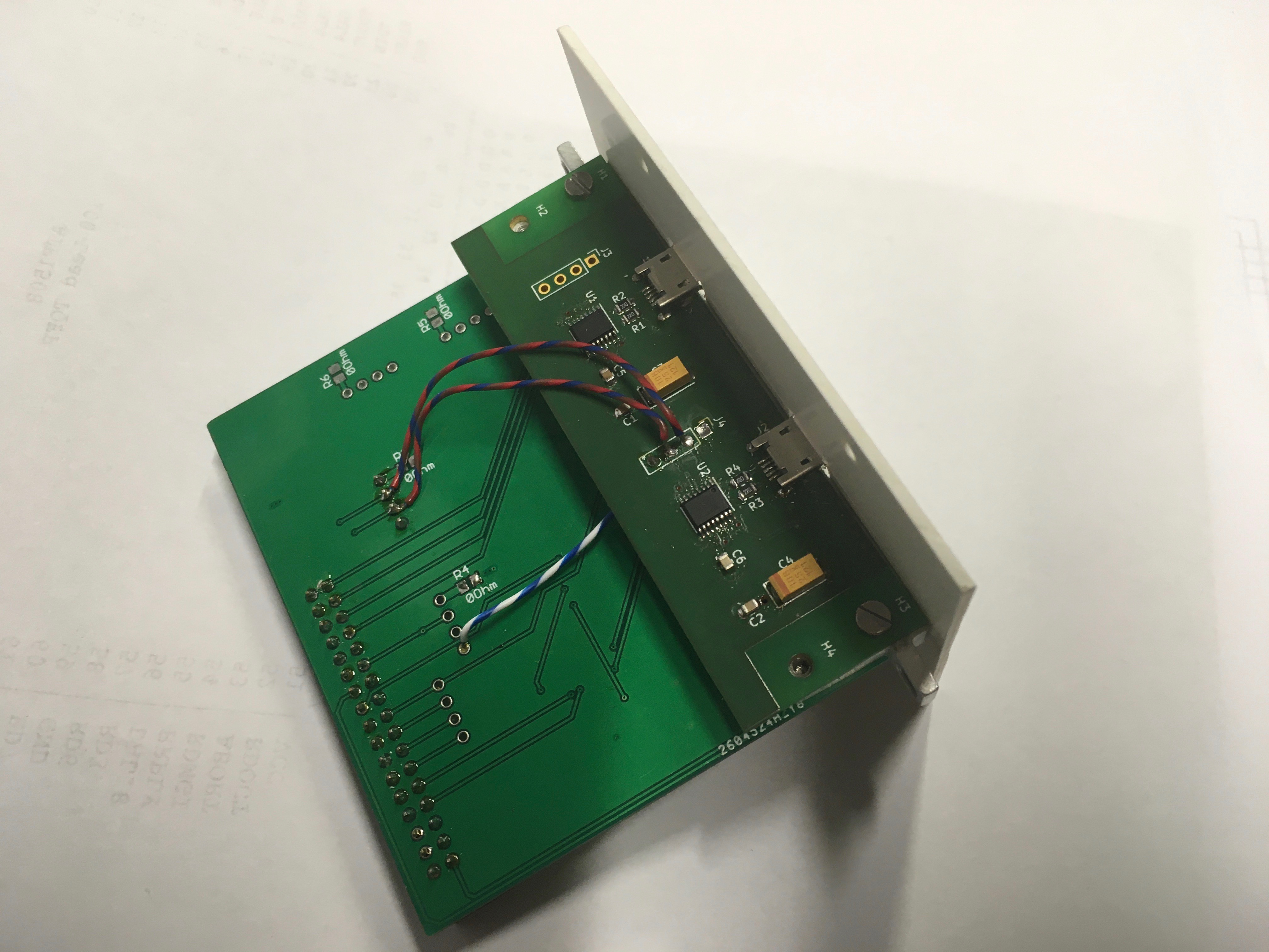
And how it looks like from the front
