System Bus
System Bus
When I was starting with the bus I was looking for an existing solution, no need to invent the wheel. Soon I found the following web site of the RetroBrew Computers which is a site about hobbyists computers based on the ECB bus. The bus seemed to fit nicely for the Q-Bus.
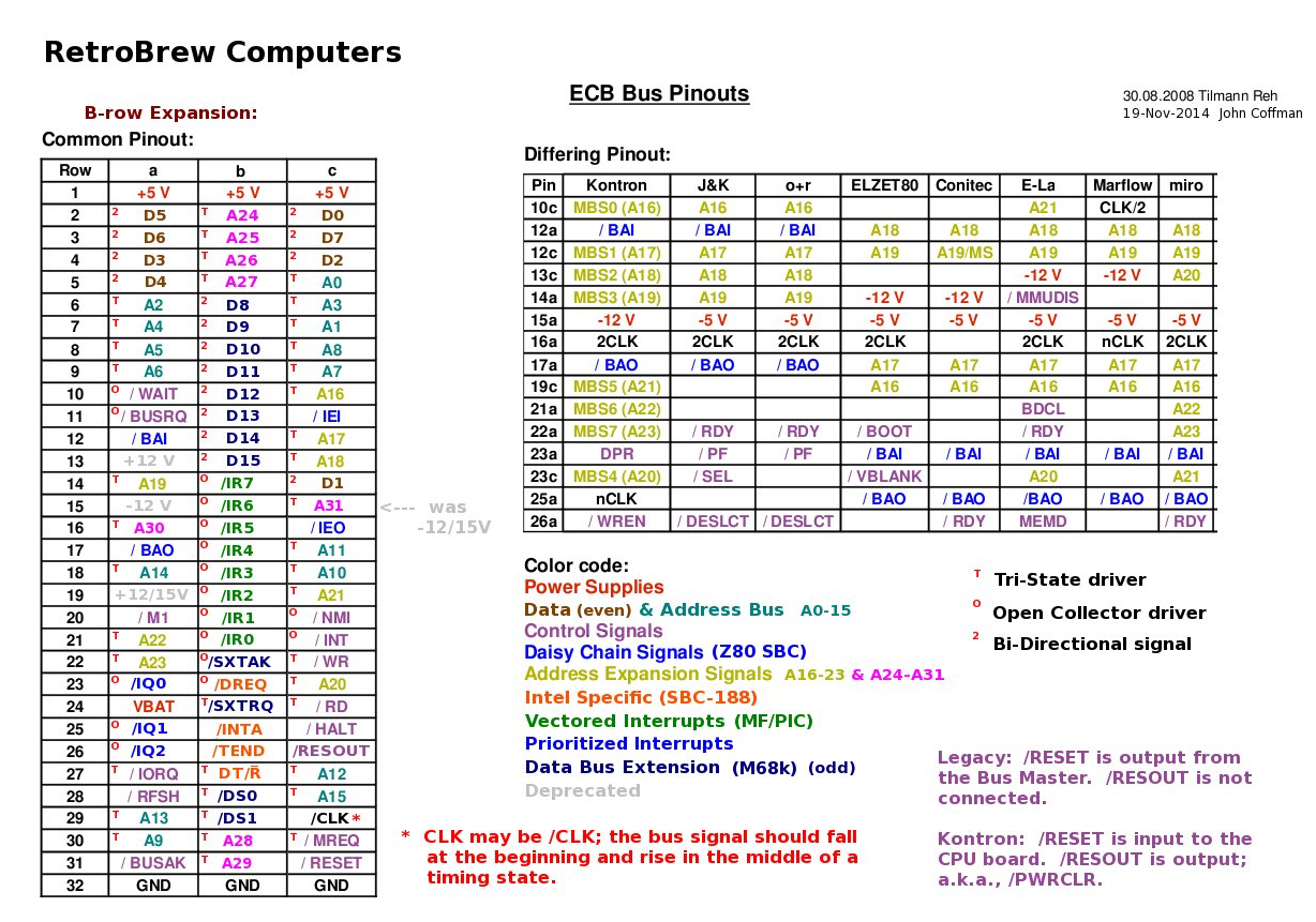
So I mapped all the Q-Bus signals to appropriate signals of the ECB bus and used it as the base for my system and named the system bus the QBUS64. This allowed me to use one of the standard bus boards available to begin with the system setup. Later I designed my own PCB. The following shows the schematic
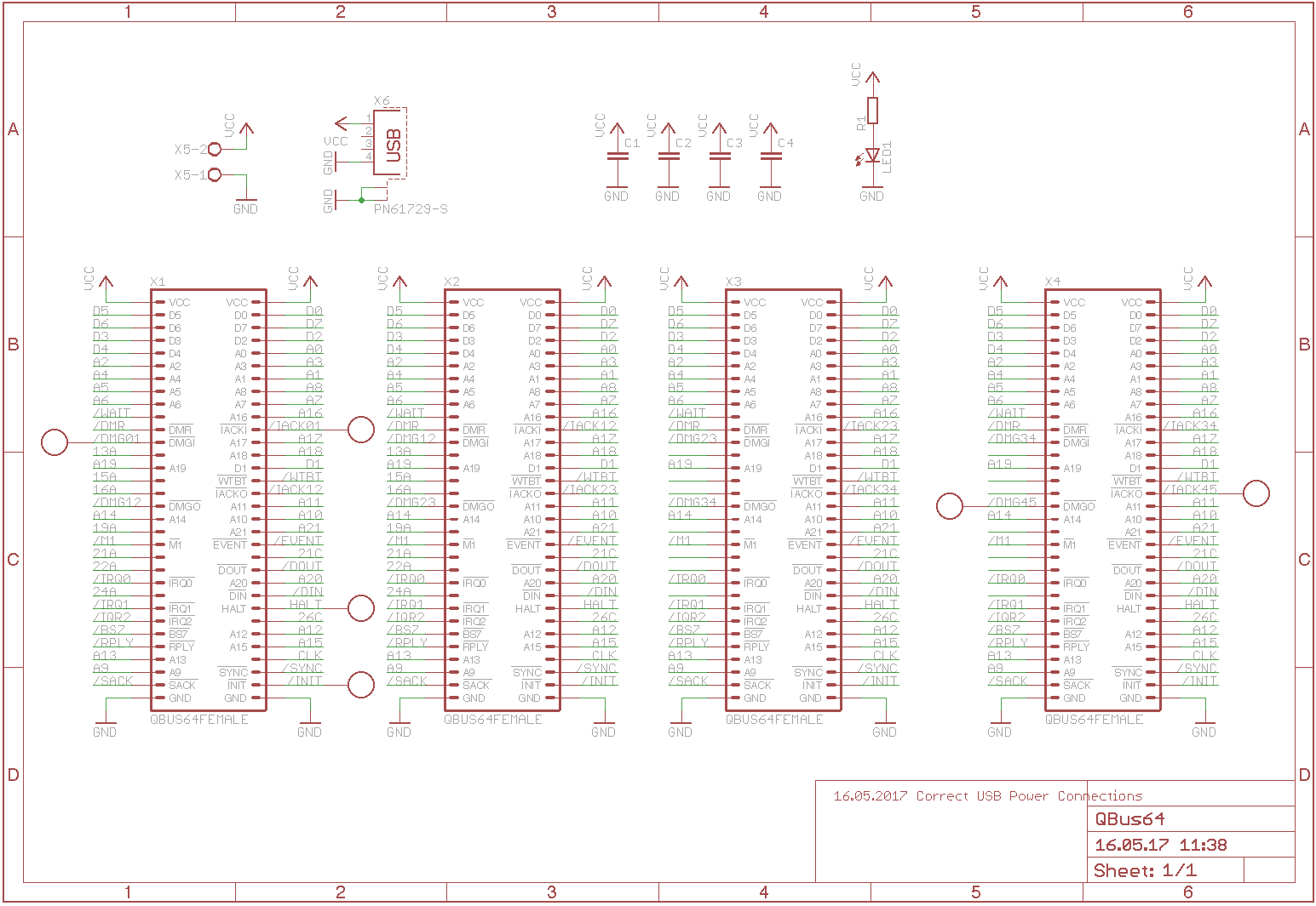
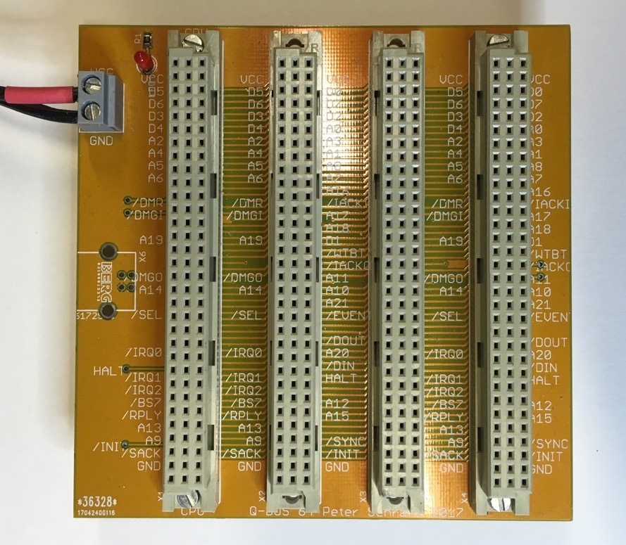
and the finished Bus of my own design.
As the real Q-Bus it is fully asynchronous. The speed is about the same as the real Q-Bus. But as with any DCJ11 based system the performance depends primarely on the memory speed. In the case of the PDP‐11/Hack the memory is located on the CPU board and operates at the speed of a cache similar to the PDP-11/93.
Please note that I often use slightly different names for the signals than are used on the Q-Bus. E.g. I did not prefix all signals with B for bus and spelt the signals differently, e.g. IACK instead of IAK, A instead of DAL, etc. This was very thoughtless. I’m continuously changing this whenever I make a new revision.
Address/Data Bus Signals
The Address and Data are multiplexed like in a real Q-Bus. However unlike the real Q-Bus the Address/Data signals use positive logic and tri-state buffers. The main reason is because the first trials on the bread-boards did not use bus transceivers. Also later the UART and the CPLD talked directly to the system bus. The UART has also positive logic. Later I tried to use an inverted bus with the CPLD but it always caused problems with WinCUPL. Might also be caused by my limited experience then with CPLD programming at that time. For a short time I was thinking about a redesign to better match the Q-Bus but then I decided it is not worth the effort and it is not necessary in case I want to translate a design to Q-Bus.
Control Bus Signals
The rest of the signals however uses open collector drivers and inverted logic. It seems natural for an asynchronous bus with a lot of bidirectional control signals and the option of multiple masters. At least it is very easy to implement the Q-Bus protocol using open collector outputs. QBUS64 uses the following Q-Bus signals:
| QBUS64 | Q-Bus | Remark |
|---|---|---|
| SYNC | BSYNC | Address Latch |
| DIN | BDIN | Master read data from slave |
| DOUT | BDOUT | Master write data to slave |
| WTBT | BWTBT | Multiplexed Write/Byte |
| BS7 | BBS7 | Bank Select 7 aka IO Page on a PDP-11 |
| RPLY | BRPLY | Reply from slave, acknowledge |
| IRQ0 | BIRQ4 | Interrupt request level 4, currently all boards use this level |
| IRQ1 | BIRQ5 | Interrupt request level 5 |
| IRQ2 | BIRQ6 | Interrupt request level 6 |
| IACKI | BIAKI | Interrupt Acknowledge In Daisy-Chain |
| IACKO | BIAKO | Interrupt Acknowledge Out Daisy-Chain |
| DMR | BDMR | DMA Service Request |
| SACK | BSACK | DMA Service Request Acknowledge |
| DMGI | BDMGI | DMA Grant In Daisy-Chain |
| DMGO | BDMGO | DMA Grant Out Daisy-Chain |
| EVENT | BEVNT | Cyclical Event, System Tick |
| INIT | BINIT | Initialise |
| HALT | BHALT | CPU Halt |
The QBUS64 does not implement or does not make use of the following signals
- BPOK
- BDCOK
- BREF
- BIRQ7
The open collector signals are only terminated on the CPU board. The bus is too short to require termination on both sides. Also I do use a 3.3V voltage and a single pull-up resister, this is the electrical equivalent to the voltage divider setup of the Q-Bus and saves a lot of power. Modern SCSI terminators for example used the same trick.
Errata
Initially I thought it would be a good idea to power the system via an USB power supply and therefore added a Type-B connector to the PCB, however I swapped GND and VCC which makes this option unusable. Don’t solder the connector, just use the screw heads as you can see on the picture.