Project Background
When in the late 90s my PRO 380 broke I removed (desoldered) the DCJ11 from the motherboard and kept it as a souvenir for many years. Back in 2014 I was asking myself whether this chip was still functional and whether it would be possible to build some sort of minimal system, like a microcomputer of the 70s. Little did I know to what extent this project would evolve. Apparently I was not the only one with the same thoughts. I soon found out that Brent Hilpert not only had the same idea but also built a minimal system using a DCJ11, some glue logic, memory and a CDP6402 UART to build a minimalistic system on a breadboard. In May 2014 he wrote a small description about his project and published it on his web site. The really minimal amount of glue logic required and the immediate success of his setup had me very confident about my own goals. I was starting to study the data sheet of the DCJ11, which is available as PDF in the internet on bitsavers, to understand what Brent has done and soon I was building my own system with my own glue logic. Like Brent’s prototype I was also using breadboards.
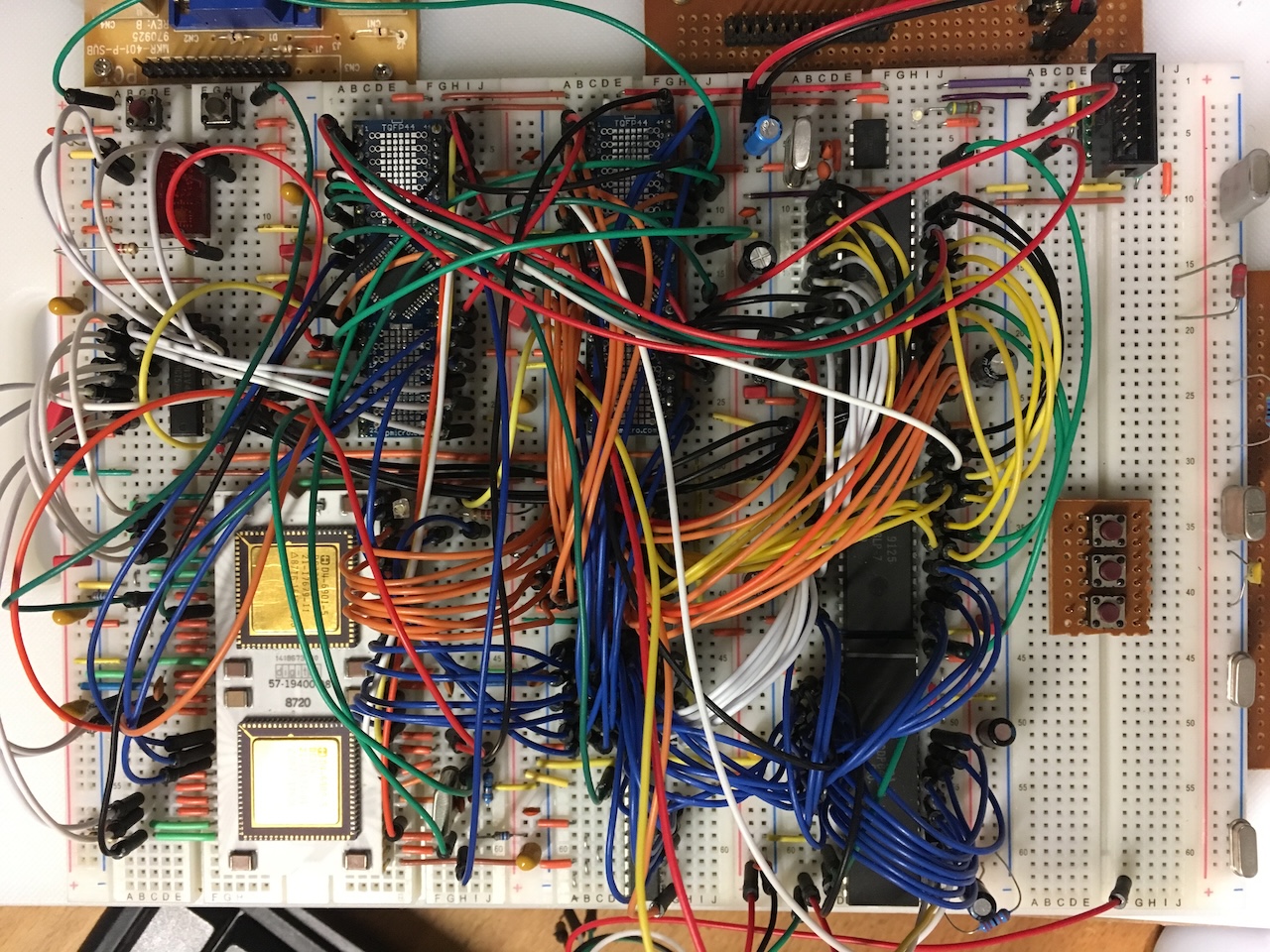
The following is a picture of the final breadboard version. This version
implemented byte write, bus time-out and interrupts.
The good thing about the DCJ11 is, that it comes with a built-in console monitor called ODT. For a minimal system some memory and a serial port that looks like a standard PDP-11 serial interface is all you need and you already can enter small programs and run them. Using Jörg Hoppes PDP11GUI comes very handy for this purpose. Soon after the first success I started to add functions that were missing in Brent’s design, like byte write support, bus timeout and interrupt capabilities. All this could be achieved with very little effort and therefore I decided to start to build a real PDP-11. Sounds complicated but in fact it isn’t.
First I needed an architecture. As the goal was to make a real™ PDP-11 system I decided to use the Q-Bus bus protocol but used an ECB type of physical layout. The first boards built was a DLV11 compatible console and the CPU board V1. To save space and have some flexibility the glue logic was no longer using GALs but instead I started to use CPLDs.
Next I added a second DLV11 and was able to successfully boot into RT-11. That’s when the project really started. A second CPU board version, which added EVNT and DMA was built and a multifunction board that included a line time clock, BOOTROM and 4 SLUs replaced the previous setup. At the end I built my RLV12 emulator to make it a complete system that now not only booted RT-11 but as well RSX-11M-Plus.