Building Instructions and Installation
Building Instructions
BOM
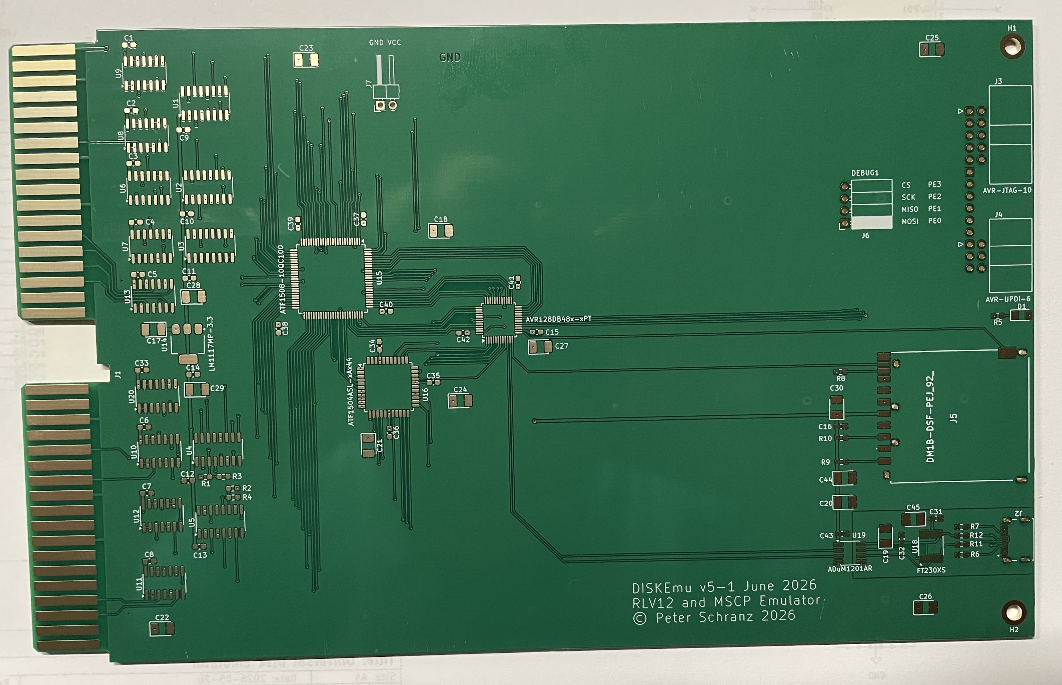
Most components are SMD devices. You need to pay special attention to select the device with the correct footprint. Many components are available in various footprints. The ceramic capacitors and the resistors have the size 0603. The electrolytic capacitors have the size 3528-12 (3.5 x 2.8 mm and 1.2mm higth.). For the TTL and HCMOS devices I used the 3.9mm narrow SOIC packages, the same goes for the ADUM1201. The FT230XS uses a SSOP-16 package. The CPLDs and the microcontrollers are all TQFP packages. The ATF1508 uses a TQFP-100 package, the ATF1504 uses a TQFP-44 package and the AVR128DB48 uses a TQFP-48 package.
You do not need to install anything for the two debug headers J6 and J8. They were only used during development. R8, R9 and R10 are not really required.
| BOM Disk Emulator V5-1 | |||
| Reference | Qty | Value | Footprint |
| C1,C2,C3,C4,C5,C6,C7,C8,C9,C10, C11,C12,C13,C14,C15,C16,C33, C34,C35,C36,C37,C38,C39,C40, C41,C42,C43 | 27 | 100n | 0603 |
| C17,C18,C19,C20,C21,C22,C23,C24, C25,C26,C27,C28,C29,C30,C44,C45 | 16 | 4u7 | EIA-3528-12 |
| C31,C32 | 2 | 220n | 0603 |
| D1 | 1 | LED | 1208 |
| J2 | 1 | USB4215-03-A_REVA | GCT USB4215-03-A-REVB |
| J3 | 1 | AVR-JTAG-10 | IDC-Header_2x05_P2.54mm_Horizontal |
| J4 | 1 | AVR-UPDI-6 | IDC-Header_2x03_P2.54mm_Horizontal |
| J5 | 1 | DM1B-DSF-PEJ_92_ | DM1B-DSF-PEJ92 |
| J7 | 1 | POWER | PinHeader_1x02_P2.54mm_Horizontal |
| R1,R2 | 2 | 680 | 0603 |
| R3,R4 | 2 | 330 | 0603 |
| R5 | 1 | 120 | 0603 |
| R6,R7 | 2 | 5k1 | 0603 |
| R8,R9,R10 | 3 | 2k2 | 0603 |
| R11,R12 | 2 | 27R | 0603 |
| U1,U2,U3,U4,U5 | 5 | 4049 | SOIC-16_3.9x9.9mm_P1.27mm |
| U6,U7,U8,U9,U10,U11,U12,U13,U20 | 9 | 74F38 | SOIC-14_3.9x8.7mm_P1.27mm |
| U14 | 1 | LM1117MP-3.3 | SOT-223-3_TabPin2 |
| U15 | 1 | ATF1508-10QC100 | TQFP-100_14x14mm_P0.5mm |
| U16 | 1 | ATF1504ASL-xAx44 | TQFP-44_10x10mm_P0.8mm |
| U17 | 1 | AVR128DB48x-xPT | TQFP-48_7x7mm_P0.5mm |
| U18 | 1 | FT230XS | SSOP-16_3.9x4.9mm_P0.635mm |
| U19 | 1 | ADuM1201AR | SOIC-8_3.9x4.9mm_P1.27mm |
PCB
The PCB has been created using KiCAD. I have ordered my PCBs with JLCPCB. I use the Fabrication Toolkit plug-in of KiCAD from JLCPCB to generate then necessary production files.
Note that the TQFP packages have 0.5mm and 0.8mm pitch, the SSOIC packages have 0.635mm pitch. If you solder them by hand I highly recommend that you use sufficient flux, it makes soldering much easier. The key is an exact placement before you tag the first two or three pins.
When soldering SMD you should always start with the components that have the lowest profile.
After soldering a good inspection is recommended. You can use the pins GND and VCC to check if the power consumption is reasonable. With all components installed the board should not draw more than 150mA. Use a power supply with current limiter the first time you power up the board.
You can program the CPLD and microcontroller when the PCB is powered up using these pins, which I recommend, to avoid issues with your Q-Bus systems because of undefined signal behaviour when the CPLDs are not programmed.
The serial interface for the microcontroller is galvanically isolated. This is to avoid any current from the host to the PDP-11 even if the PDP-11 is switched off. I have had often issues with leakage current on RX and TX signals and hence I often use an isolator to avoid any random behaviour of microcontrollers. Modern microcontroller use only little current and in this case only 1.8V operation voltage, or in other words, the microcontroller would operate with the current injected by the serial TX line over the protection diode of the chip.
Note that the ADUM1201 is not specified for isolation against mains, you still need to properly ground the PDP-11 and your host system.
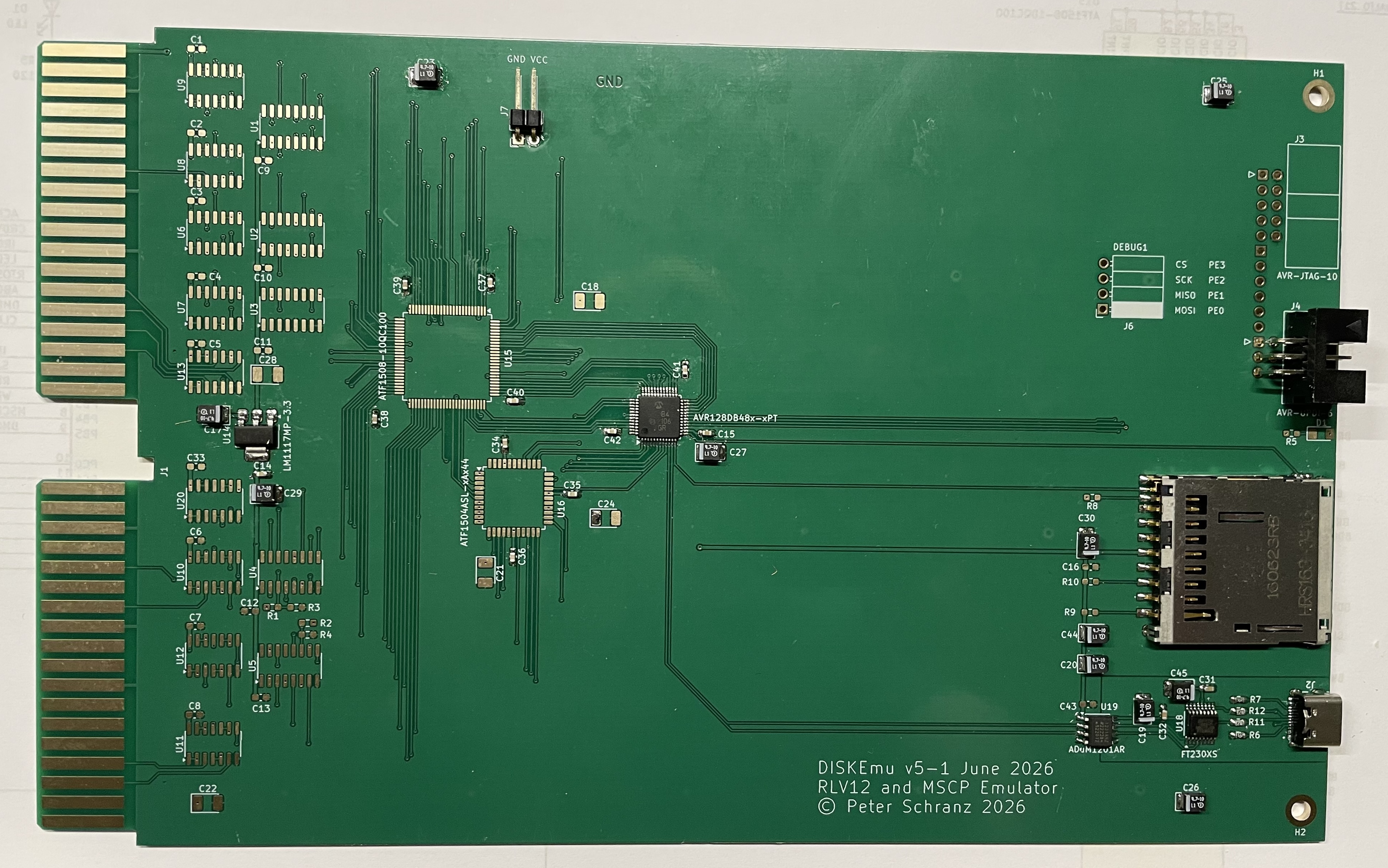
Building Process
We are starting by inspecting the empty PCB, now ist the best time to chamfer the card edge. The chamfer angle should be 60°.
First I install microcontroller, power regulator, SD-Card and the USB section. I also install the UPDI programming connector and some decoupling capacitors and the auxiliary power connector in order to be able to start testing. Now you can apply 5V power to the auxiliary power pins labeled GND and VCC. Always use some sort of current limiter. The board should not consume more than 10mA now. In this stage you could also try to load the firmware and connect you computer with a USB cable. After loading the firmware you should be able to see a prompt and enter commands. Also when you now insert a MBR formatted SD-Card you should see the microcontroller trying to access and read the SD-Card. The serial port settings are 115200baud, 8 bit data no parity, one start and one stop bit without handshaking.
In a next phase I installed the CPLDs, some more de-coupling capacitors and the JTAG programming connector. Again when you now apply power you should first use some sort of current limiting. The CPLDs may draw up to 100mA if erased. This is a good opportunity to programm the CPLDs.
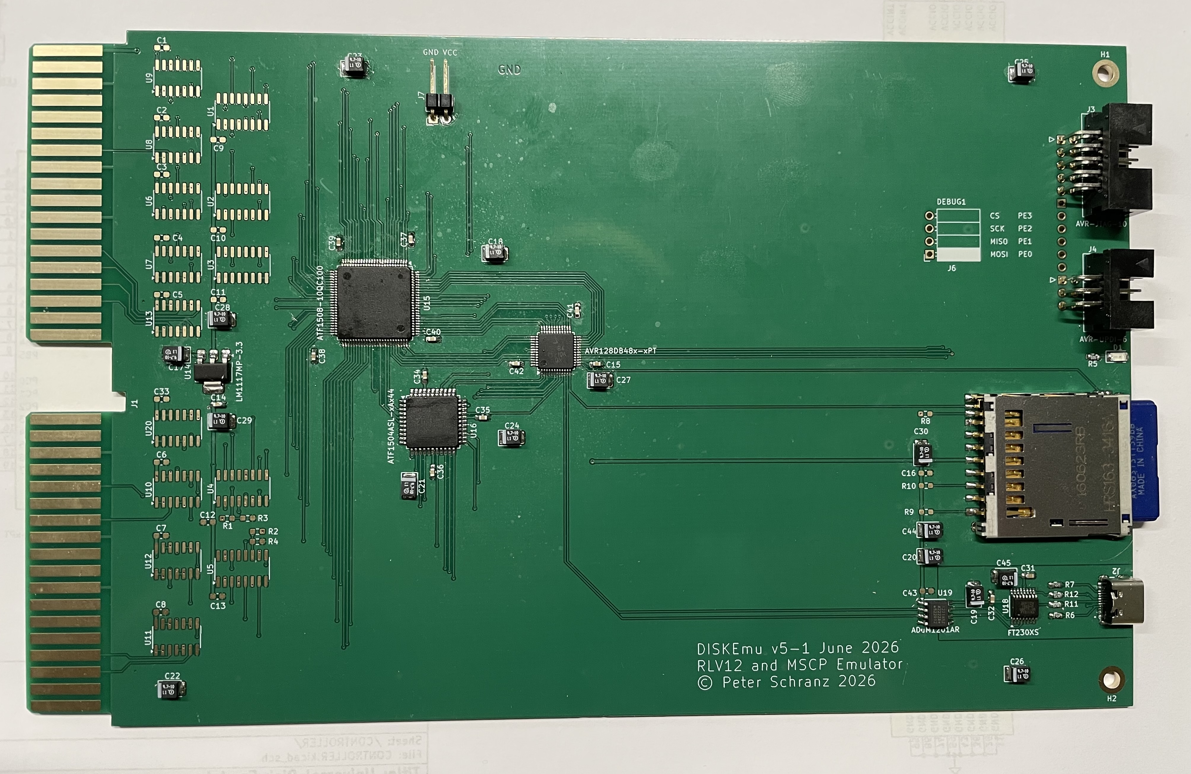
You can now use the dmadata command to test the communication between the
CPLD and the microcontroller. With this command the microcontroller writes
a value to the DMA data register and reads it back. Of course the value
read back should be the same as you entered with the command. Note that the
command accepts the number in standard decimal, hex and octal commands. It
displays the value read back in hex.
]dmadata 0
DMA Register read back 0x0000

]dmadata 0xffff
DMA Register read back 0xFFFF

]dmadata 0x00ff
DMA Register read back 0x00FF

]
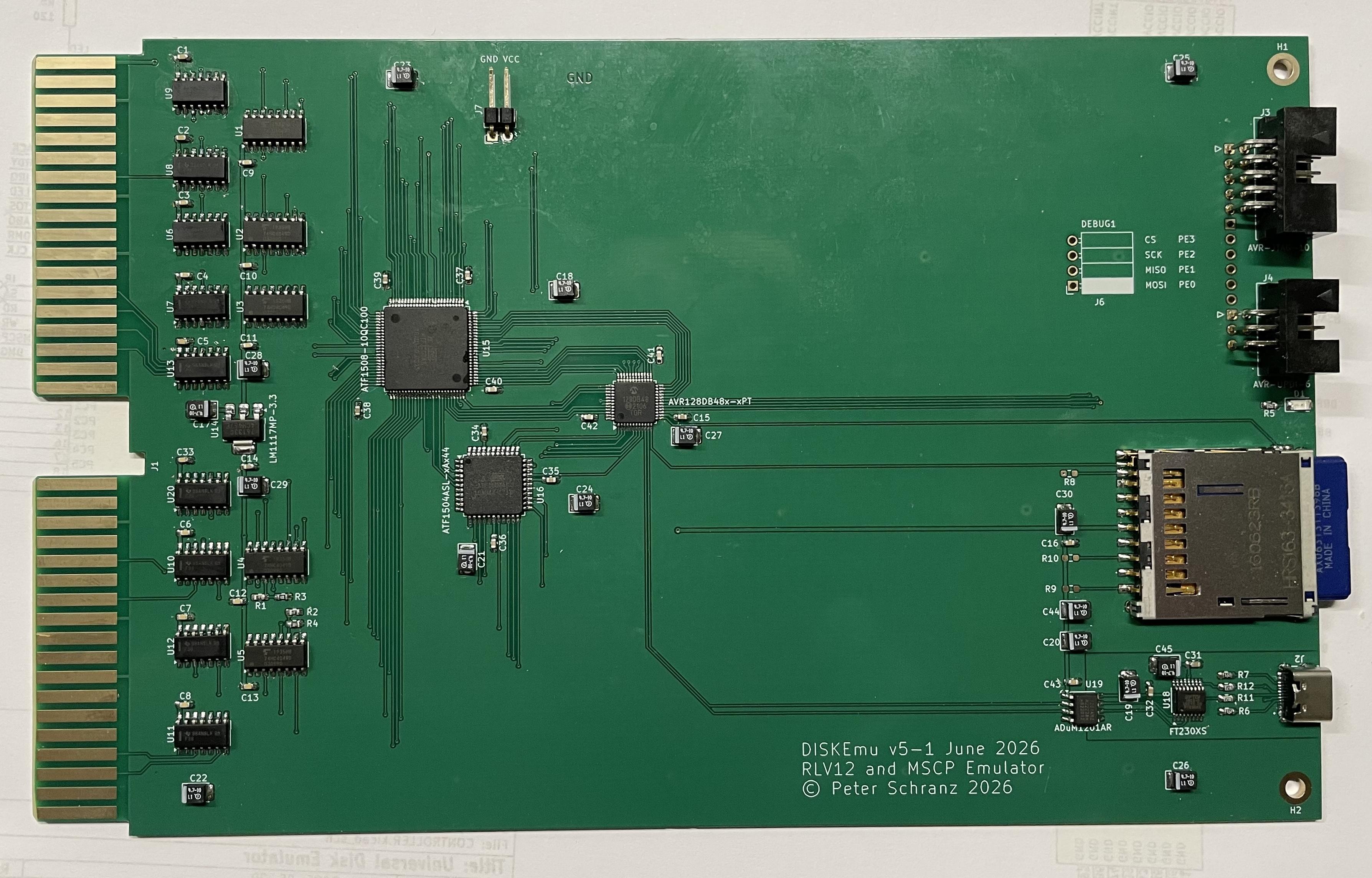
Now you can install the remaining components, the 74F38, the 74CD4049 and the rest
of the de-coupling capacitors and the termination resistors for BIAKI and BDMGI.
Check again using the auxiliary power input and if everything is ok you can now
insert the controller into your Q-BUS backplane.
Programming the CPLD
The CPLDs used are ATF150x from Microchip. The main purpose for which I uses these CPLDs is that they are still available as 5V devices. To program the CPLDs I use ATMISP 7.3 which is available for free on the Microchip website. The software is Windows only. To be able to use this software I’m running Windows 11 on ARM in a virtual machine using VirtualBox from Oracle which is available for free. However the setup on Windows on ARM is very tricky as ATMISP is a x86 program and you need to install the FTDI device drivers for the USB serial chips used in the programmer. As I’m using a MacIntosh with M3 processor, Windows on ARM is almost the only option to use Windows. Another issue is that the only USB JTAG programmer ATMISP supports is the ATDH1150.
To create the JEDEC files I use WinCUPL II, which has been recently updated by Microchip and it is now Windows 11 compatible and runs very well on Windows 11.
There will be a separate article about how to compile CUPL design files and how to program the CPLDs not only using the above described method.
The straight forward solution is to use a Intel Based Windows system and the ATDH1150USB JTAG programmer and install WinCUPL and ATMISP from Microchip as described on their homepage.
CPLD Design, Chain and JEDEC Files
To program the CPLDs you need a chain file that describes how the CPLDs are connected to the JTAG programming interface and the JEDEC files. Place the chain file and JEDEC files for the two CPLDs in a directory.
Install and start ATMISP and open the chain file. Now you need to set the correct paths in the JEDEC files. Unfortunately ATMISP stores the absolute paths of the JEDEC files. When you have set the correct path save the chain file so it can be used later for updates without having to change the configuration.
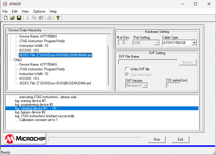
If you have not connected the ATDH1150USB programmer when you started ATMISP you need to “Scan the USB Cable” found in the “Options” menu. Make sure the MSCP emulator is connected to 5V power and the JTAG connection cable is inserted correctly.
Now you can press the execute button, the programming will takes some time and the progress bar will be updated four times. If the programming returns “JTAG instructions finished successfully” your are done.
Loading the firmware
If you want to assemble the source code yourself you need to have the AVRASM2 assembler from Microchip. The assembler is only included in Microchip Studio and can be either used in the Microchip Studio IDE or as a command line programm. As far as I know the assembler is no longer included in the MPLAB® X IDE. It was once available in version 2.0.5 and I extracted the macOS version of AVRASM2 and use this to assemble my source code.
To program the microcontroller, a AVR128DB48, you either need a genuine UDPI programmer or a simple version of it. There are many cheap versions available and as UPDI is using single wire half-duplex asynchronous communication you can even build your own version. For example the one described in the pyupdi GitHub project.
I’m currently using a ATMEL-ICE as I’m doing a lot of other projects with different microcontrollers that use other protocols.
For most cheap and self-built programmers you can use the python script pyupdi
mentioned above.
Many programmers, including the ATMEL-ICE, are supported by avrdude which I’m
using.
Microcontroller HEX and Source Files
To program the microcontroller you only need to load the HEX file. Either
use the python script pyupdi or use avrdude with any supported UPDI
programmer. See the Makefile for a command line using avrdude to load the
hex file using the Atmel-ICE universal programmer. For a list of supported
UPDI programmers see the documentation of avrdude.
Installation
Before you install the controller make sure you visually check for obvious defects. In case you have ordered the PCB without chamfered Q-Bus edge connector make sure that you file the top and bottom edge at an angle of 60°. Also be aware that having a PCB without ENIG finish the insertion and removal of the card may wear the gold plating of fingers of the Q-Bus connectors and over time the contacts may corrode which makes for open contacts. Although ENIG is not the same as hard plated gold contacts it’s at least a compromise. As long as you don’t insert and remove the card too many times this is ok.
The controller has no jumpers, the device register addresses are programmed into the CPLDs and the vector for the RLV12 emulation is part of the firmware. The vector of the MSCP emulation is dynamically configured by the host.
Insert the controller in any free slot of our standard Q-Bus system. Note that you must not use a CD slot for this controller.
Make sure that there are no gaps between the controller and the CPU, which would otherwise break the DMA Grant or Interrupt Acknowledge daisy chain.
Connect your computer using a standard USB-C cable with the serial interface on the controller and use your favorite terminal emulation program. Note that the command line interface expects standard VT100 escape sequences for cursor control to edit and recall command lines.
The baud-rate is 115'200baud and the character format is 8 bits without parity, one start and one stop bit without hardware handshake.
Be careful when inserting the controller the two shrouded programming interface connectors are at the upper limit of the allowed highth of components on the solder side and might touch the rivets or handle of cards installed above as was in my case for the memory module I used in my test system.
When you have checked the installation you can power-up your system. You should see the following output on your terminal emulation program.
RSTCTRL_RSTFR  0x01
SD-Card Status 0x00
Starting Universal Disk Controller!
Create Main Job
        Job Control Block  0x4DD0
        Initial Stack      0x4100
        Programm Start     0x07DB
        Priority/Flags     0x04/0x00

Hallo RTOS on Universal Disk Emulator
Create SD-Card Detect Job
        Job Control Block  0x4DDA
        Initial Stack      0x4200
        Programm Start     0x08DC
        Priority/Flags     0x09/0x00
Create Poll Job
        Job Control Block  0x4DE4
        Initial Stack      0x4300
        Programm Start     0x5BB2
        Priority/Flags     0x02/0x00
Create Init Job
        Job Control Block  0x4DEE
        Initial Stack      0x4400
        Programm Start     0x5512
        Priority/Flags     0x01/0x00

]
SD Card removed  0xF0 0xF8 0xFC 0xFE 0x00 0x00 0x00 0x00

]
Next step will be preparing a SD-Card and insert it into the Card Slot of the controller card.